
Variable-structure slag removal mechanism and method

A technology for removing slag and components, which is applied in the field of liquid metal slag removing mechanism, can solve problems such as increasing equipment cost, unsatisfied requirements for increased driving force, and easy failures, etc., so as to improve the service life of equipment, reduce the thermal protection level, prolong the The effect of service life

Active Publication Date: 2022-05-17
YANTAI SHENGLIDA ENG TECH
View PDF6 Cites 3 Cited by
  • Summary
  • Abstract
  • Description
  • Claims
  • Application Information

AI Technical Summary

Problems solved by technology

It has large defects and has no practical application. The main reasons are: (1) The structure is complex, the volume is large, and it is not easy to do heat insulation. Low
(2) It is heavy and requires a large driving force, which increases the cost of the entire equipment
(3) This type of connecting rod joint type slag cleaning mechanism is limited by the dead zone of the mechanism, the rotation range is limited, and it cannot rotate 180°. It can only clean the iron slag in the semicircular area. The slag cleaning range is small and the efficiency is low.
3. Unable to meet the requirements of driving force improvement for current and future efficiency improvement
4. Unable to meet current and future volume reduction and lightweight requirements

Method used


Image

  • Variable-structure slag removal mechanism and method
  • Variable-structure slag removal mechanism and method
  • Variable-structure slag removal mechanism and method

Examples


Embodiment 1

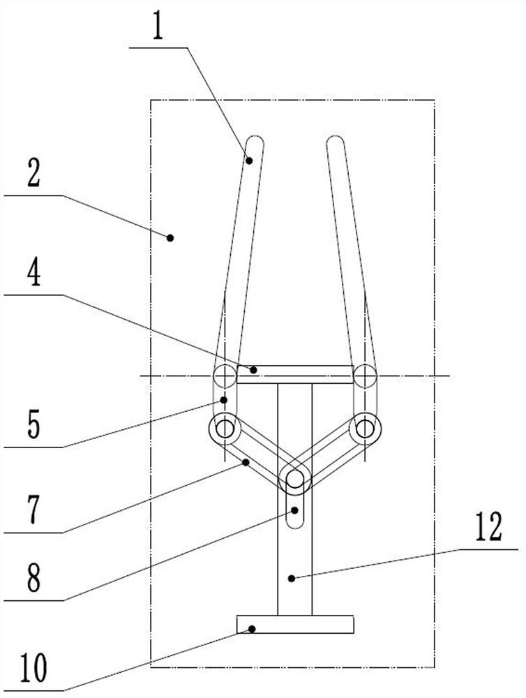
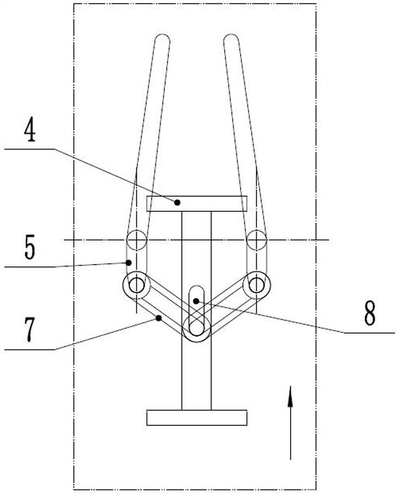
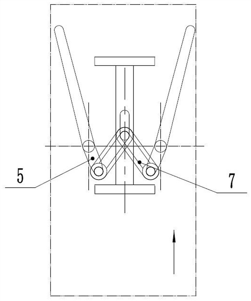
[0072] like Figure 1-10 , in this embodiment, the pulling member 7 is a rigid structural member provided with a sliding groove, the movable connection point between the crank 5 and the pulling member 7 and the movable connection point between the driving body 12 and the pulling member 7, two Or at least one of them is in the sliding groove (the end that is not in the sliding groove can be a common hinge), so that the crank 5 or the driving body 12 can rotate relative to the pulling member 7, and can also move relative to it, thereby After the front push block 4 or the rear push block 10 touches the crank 5, relative movement can occur between the movable connection point between the crank 5 and the pulling member 7 and the movable connection point between the driving body 12 and the pulling member 7 .

[0073] Further, the drive body 12 is provided with a chute 8, and the chute 8 is provided with a hinge shaft that can move back and forth along the chute 8, and the other end...

Embodiment 2

[0079] like Figure 11-22 , The difference between this embodiment and Embodiment 1 is that the pulling member 7 is a flexible member, such as a soft belt. The flexible belt can be ring-shaped or rod-shaped. If it is ring-shaped, the active connection points at both ends are in this ring-shaped groove (shaft-groove connection), and if it is not ring-shaped, both ends can be hinged.

[0080] The function of the soft belt is: after the front push block 4 or the rear push block 10 touches the crank 5, if there is a problem of mechanical interference, the soft belt (pull member 7) can be bent to make the distance between the crank 5 and the pull member 7 Relative movement can occur between the movable connection point and the movable connection point between the driving body 12 and the pulling member 7, thereby resolving the interference, so that the crank 5 moves completely under the action of the push block.

[0081] Another difference between this embodiment and Embodiment 1 i...

Embodiment 3

[0088] The concept of this embodiment is quite different from the above embodiments: the pulling member 7 is a rigid connecting rod, and both ends are hinged, but the hinge shaft connected to the end of the driving body 12 is along the drive The chute 8 on the body 12 is movable, and in order to ensure normal pulling, the driving body 12 is also provided with an elastic mechanism.

[0089] Specifically, such as Figure 23 , The driving body 12 is also provided with a chute 8 running forward and backward, and two groups of slag pickers 1 , pulling members 7 and cranks 5 are arranged symmetrically with respect to the chute 8 . The other ends of the two pulling members 7 are connected to the hinge shafts arranged in the chute 8 to realize the respective rotation of the two pulling members 7 relative to the chute 8 and the forward and backward movement of the hinge shaft along the chute 8 .

[0090] The driving body 12 is also provided with a front spring 3 , a front push plate 6...


PUM


Abstract

The invention discloses a variable-structure slag removal mechanism and method. The slag removal mechanism comprises a body and two groups of symmetrically arranged slag scrabbles, the slag scrabbles and the body can rotate relatively, and the slag removal mechanism further comprises a driving body, a traction component and a crank; the driving body is installed on the body in a sliding fit mode so as to move front and back. Each slag scraper corresponds to a group of traction components and cranks, one end of each crank is rotationally connected with the body and fixedly connected with the slag scraper, and the other end of each crank is movably connected with one end of the corresponding traction component; the other end of the traction component is movably connected with the driving body; a front push block and a rear push block are arranged on the driving body; the front push block and the rear push block are respectively used for pushing the crank backwards and forwards; and the traction component is used for transmitting the traction force of the driving body to the crank so as to drive the slag scraper to rotate. The invention further discloses a slag removal method based on the slag removal mechanism. The slag removal device has the advantages of simple structure, small size, light weight, long service life, large slag removal force, large working condition application range and the like.

Description

technical field [0001] The invention relates to a mechanism for removing slag from molten metal, and also relates to a method for removing slag from molten metal. Background technique [0002] There are mainly two ways to remove slag from molten metal: slag removal and slag removal. The traditional slag removal mechanism mainly has the following problems: 1. The slag removal is driven by a huge connecting rod mechanism or a transmission structure such as a gear or a rack, which is bulky and heavy. 2. A typical structure such as the German patent "Rapid slag removal from melts, esp molteniron - using scraper fitted with blades mounted on pivots" with the publication number DE2539512: using two sets of operating rods that move back and forth, through complex rotating joints The structure drives the slag picker to move. It has large defects and has no practical application. The main reasons are: (1) The structure is complex, the volume is large, and it is not easy to do heat ...

Claims


Application Information

Patent Timeline
Patent Type & Authority Applications(China)
IPC IPC(8): B22D43/00
CPCB22D43/007Y02P10/20
Inventor 盛富春盛镝
Owner YANTAI SHENGLIDA ENG TECH
Learn More