Portable mounting structure of motor for new energy automobile and motor for new energy automobile

A new energy vehicle and installation structure technology, applied in electric vehicles, electric power units, power units, etc., can solve the problems of affecting the installation efficiency of automotive motors, increasing the difficulty of installation, and cumbersome installation methods, so as to improve convenience and shorten the Installation time, the effect of reducing quality requirements

Active Publication Date: 2022-05-17
无锡泓阳电动科技有限公司
View PDF25 Cites 0 Cited by
  • Summary
  • Abstract
  • Description
  • Claims
  • Application Information

AI Technical Summary

Problems solved by technology

[0004] The purpose of this application is to provide a portable installation structure for a new energy vehicle motor and a new energy vehicle motor, so as to solve the problem that the installation method of the existing vehicle motor is easily affected by the work quality of the staff during the operation process. Irregular operation can easily lead to major safety accidents. At the same time, the internal structure of the vehicle body is complex, which increases the difficulty of installation, and the installation method is cumbersome, which seriously affects the installation efficiency of vehicle motors.

Method used


Image

  • Portable mounting structure of motor for new energy automobile and motor for new energy automobile
  • Portable mounting structure of motor for new energy automobile and motor for new energy automobile
  • Portable mounting structure of motor for new energy automobile and motor for new energy automobile

Examples


Embodiment

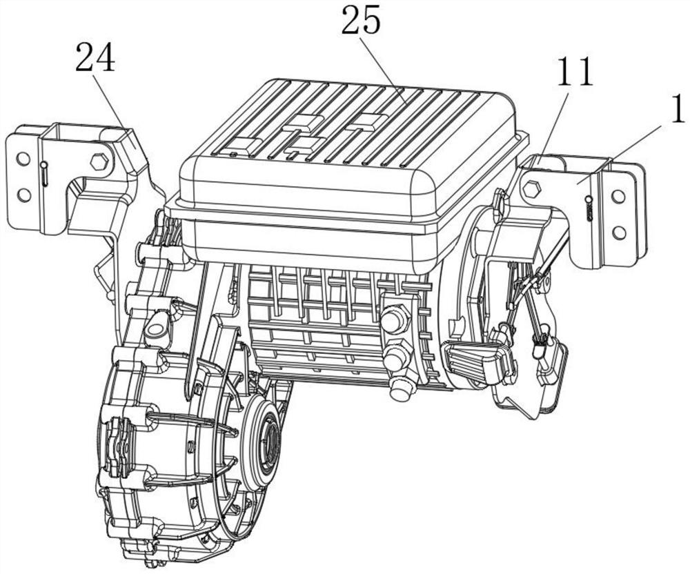
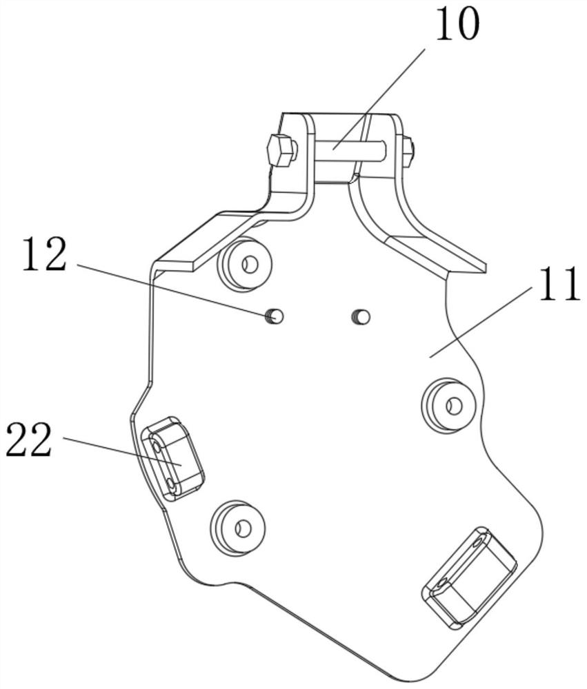
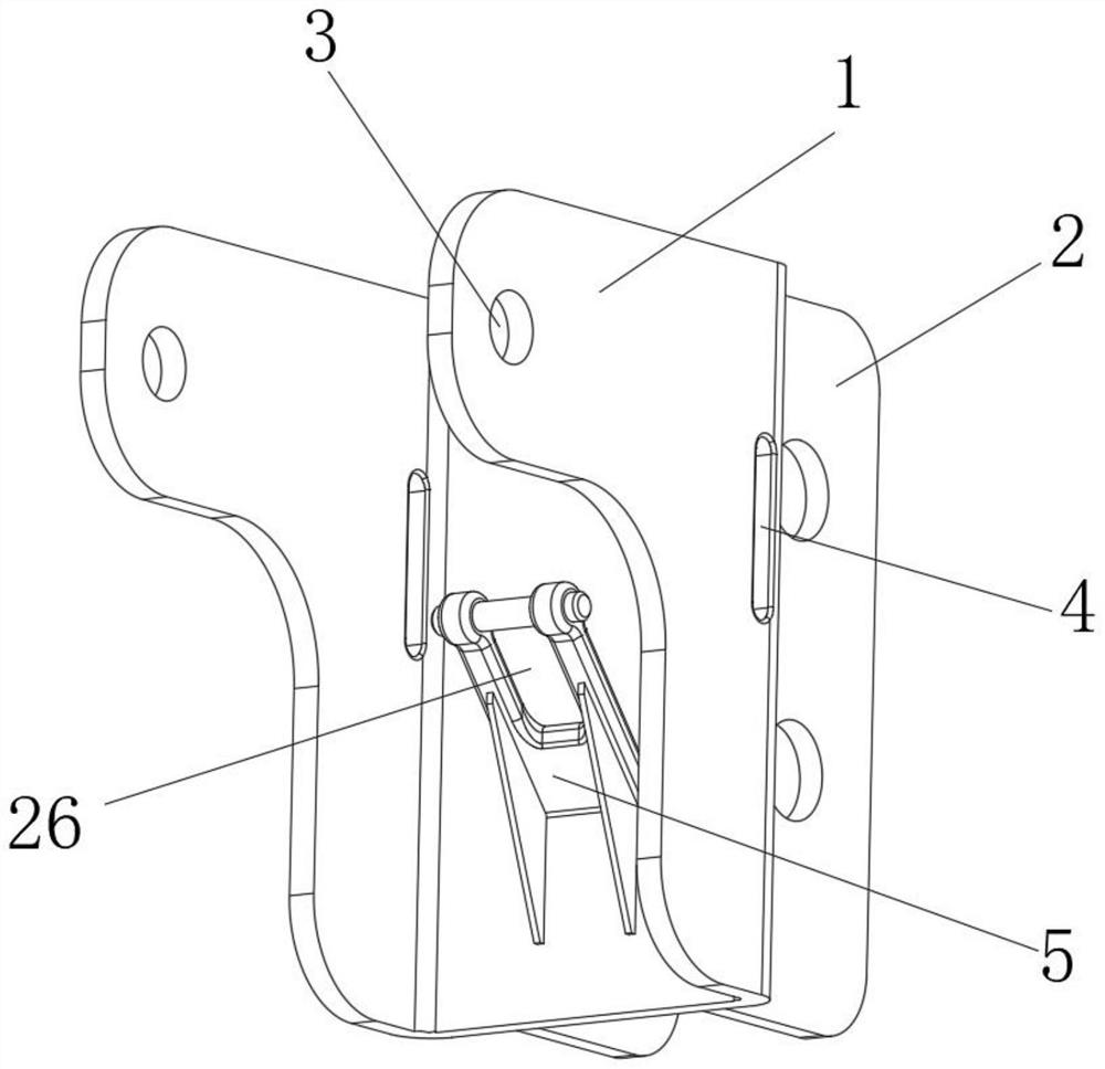
[0034] Example: Reference Figure 1-7 The illustrated portable installation structure for a new energy vehicle motor includes two fixing brackets 1, one side of the two fixing brackets 1 is provided with connecting holes 3, and the two connecting holes 3 are fixedly sleeved with fixing bolts 10. , the outer sides of the two fixing bolts 10 are respectively rotated and socketed with a first guide plate 11 and a second guide plate 24, and one side of the first guide plate 11 and the second guide plate 24 are provided with a number of limit holes, new energy vehicles Both sides of the motor body 25 are provided with some mounting holes that are compatible with the limit holes; supporting parts are installed on the fixed bracket 1, and connected transmission parts and limit parts are installed on the first guide plate 11, such as Figure 4 As shown, the side supporting part on the fixed bracket 1 on one side of the motor 25 is connected to the transmission part, and the side suppo...


PUM


Abstract

The invention discloses a portable mounting structure of a motor for a new energy automobile and the motor for the new energy automobile, the portable mounting structure comprises two fixing supports, one side of each fixing support is provided with a connecting hole, and fixing bolts are fixedly sleeved in the two connecting holes. According to the motor portable installation structure for the new energy automobile and the motor for the new energy automobile, the quality requirement for workers in the motor installation process is lowered, and meanwhile, the situation that the workers conduct non-standard operation such as guiding on the suspended motor through limbs and the like, and consequently a large safety accident is caused is avoided; the influence of a complex structure in the frame on the installation process and the installation difficulty of the motor are reduced, the installation mode is simple, disassembly and maintenance of the motor are facilitated, the installation efficiency of the motor body is improved, and the situation that in the installation process of the motor body, workers need to continuously adjust fixing holes to be aligned with limiting holes is avoided; the installation efficiency of the motor body is further improved, and the workload of workers is reduced.

Description

technical field [0001] The invention relates to the technical field of motors, in particular to a portable installation structure for a motor for a new energy vehicle and a motor for a new energy vehicle. Background technique [0002] The motor is the driving machine of the electric vehicle. Because the electric vehicle uses the power battery as the vehicle energy source, its capacity is limited. In order to extend the mileage as much as possible, most drive systems adopt energy feedback technology, that is, when the vehicle brakes, The kinetic energy lost by the wheels is fed back to the battery through the controller, and the motor is in a power generation state, and the generated electricity is delivered to the battery. [0003] Most of the existing motors for new energy electric vehicles are three-in-one motors, with many integrated parts and heavy weight. Generally, hoisting tools are used to hoist the motor. Auxiliary to align the relevant installation points on the m...

Claims


Application Information

Patent Timeline
Patent Type & Authority Applications(China)
IPC IPC(8): B60K1/00
CPCB60K1/00Y02T10/70
Inventor 陈泓
Owner 无锡泓阳电动科技有限公司
Why Eureka
Try Eureka