Full-section hard rock tunnel boring machine

A tunnel boring machine, full-section technology, used in tunnels, mining equipment, earth-moving drilling, etc.

Pending Publication Date: 2022-05-17
CHINA RAILWAY ENGINEERING EQUIPMENT GROUP CO LTD
View PDF0 Cites 0 Cited by
  • Summary
  • Abstract
  • Description
  • Claims
  • Application Information

AI Technical Summary

Problems solved by technology

[0004] The purpose of the present invention is to provide a full-face hard rock tunnel boring machine to solve the technical problem that the cutter head of the TBM in the prior art is easily jammed by the gravel when the TBM is driving in the hard rock crushing area.

Method used


Image

  • Full-section hard rock tunnel boring machine
  • Full-section hard rock tunnel boring machine
  • Full-section hard rock tunnel boring machine

Examples


specific Embodiment 1

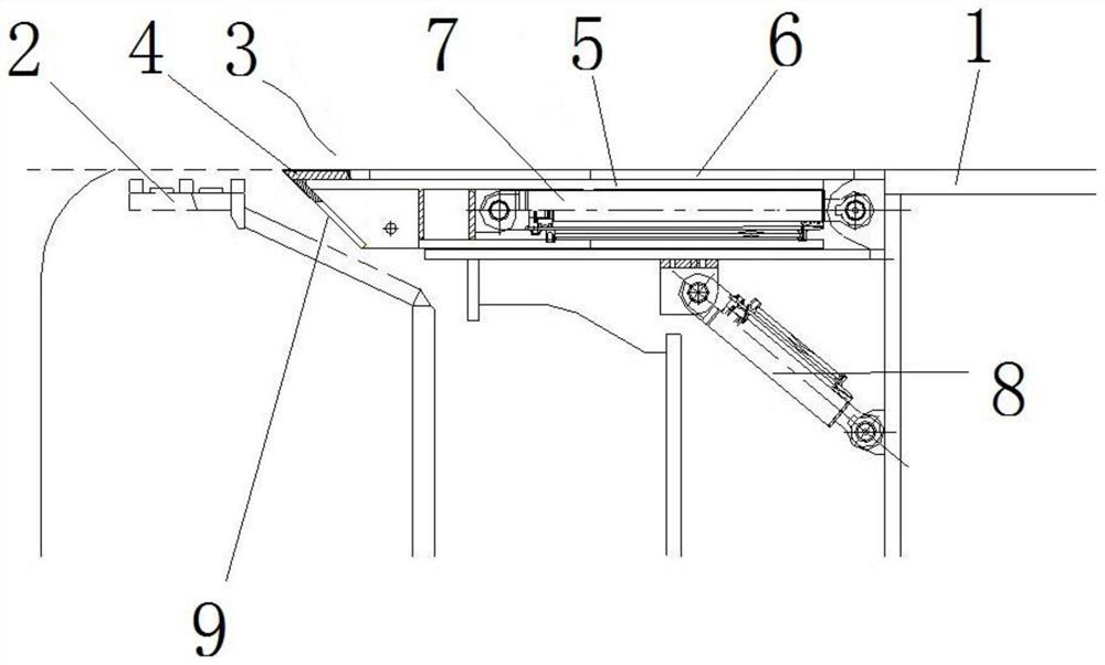
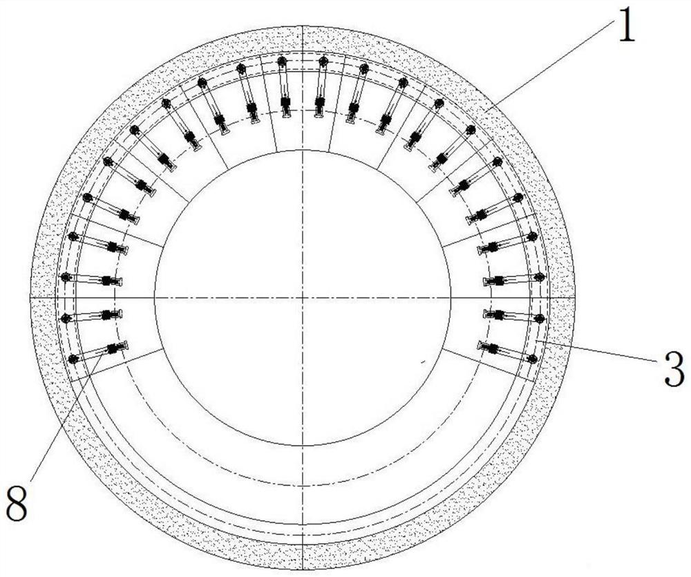
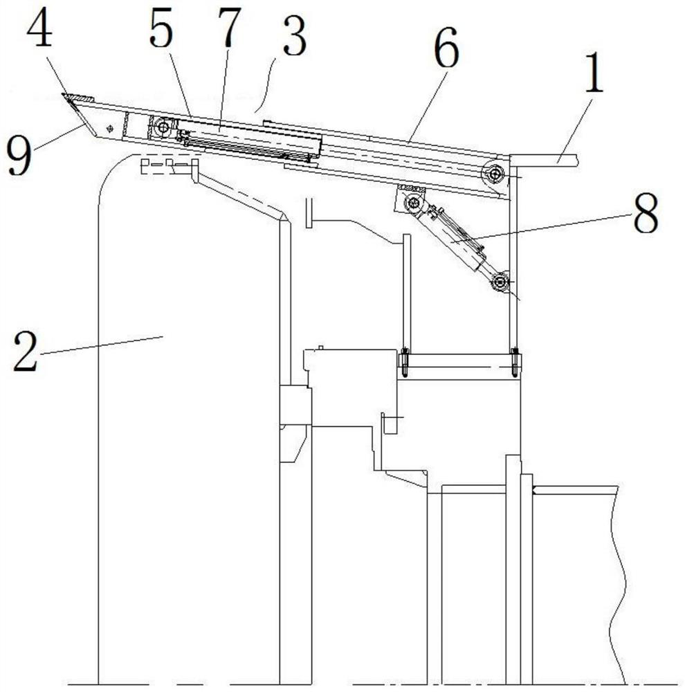
[0035] as Figures 1 through 4 As shown, the full-section hard rock tunnel boring machine comprises cutterhead 2 and a shield located behind cutterhead 2, the shield comprises shield 1, and in shield 1 there is a main drive that drives the cutterhead 2 to rotate. Among them, there is a knife insertion protection mechanism in the shield behind cutterhead 2, and the knife insertion protection mechanism is supported in the extension direction parallel to the shield when the full-section hard rock tunnel boring machine is in a normal boring state, so as to be used as a shield 1 shell on the back side of cutterhead 2, at this time the insertion knife drive mechanism is in a horizontal protection state. When the full-section hard rock tunnel TBM is in the tunneling condition of the falling rock crushing zone, the control knife insertion protection mechanism is expanded outwards, thereby forming a circular support on the outward side of the cutterhead for 2 weeks to prevent the cutterhead...

specific Embodiment 2

[0045]The difference from Example 1 is that, in Example 1, one end of the insert knife 3 is in the pendulum arm 6 and the lumen of the swing arm 6 is coordinated with the anterior and posterior guides. In the present embodiment, both ends of the insertion knife are within the swing arm, i.e., when the insertion knife protection mechanism is located in a horizontal protection state, the insertion knife as a whole is submerged into the inner cavity of the swing arm.

specific Embodiment 3

[0047] The difference from Example 1 is that, in Example 1, one end of the swing arm drive cylinder 8 is hinged on the side of the swing arm 6 towards the inside of the shield 1, the other end is hinged on the shield 1, the swing arm drive cylinder 8 is arranged obliquely in the shield 1 so that the swing arm drive cylinder 8 can be directly ejected out of the shield 1 when extended. In the present embodiment, in order to ensure the swing arm driving cylinder under conventional working conditions on the swing arm support effect, and further protect the swing arm drive cylinder, the swing arm drive cylinder and the swing arm between the additional leverage mechanism, through the transfer of the upper force of the lever mechanism will be the swing arm up, the lever mechanism can greatly reduce the pressure of the swing arm, thereby protecting the swing arm drive cylinder, while reducing the top thrust of the cylinder, increasing the service life, the lever mechanism can be a small c...


PUM


Abstract

The invention aims to provide a full-section hard rock tunnel boring machine to solve the technical problem that a cutter head is easily blocked by collapsed broken stones when a TBM (Tunnel Boring Machine) is used for tunneling in a hard rock crushing area in the prior art. The full-section hard rock tunnel boring machine comprises a cutterhead and a shield, the shield comprises a shield body, a main drive and slotting tool protection mechanisms are arranged in the shield body, the slotting tool protection mechanisms are arranged at intervals in the circumferential direction of the shield body, each slotting tool protection mechanism comprises a swing arm hinged to the shield body, and a swing arm driving mechanism for driving the swing arm to swing in a pitching mode is connected to the swing arm. A slotting tool is movably installed on the swing arm in the length direction of the swing arm. The swing arm is further provided with a slotting tool driving mechanism for driving the slotting tool to reciprocate in the length direction of the swing arm, and after the swing arm driving mechanism drives the swing arm to swing towards the outside of the shield body, the slotting tool driving mechanism can drive the slotting tool to move forwards to be inserted into surrounding rock on the front side of the swing arm from the radial outer side of the cutter head.

Description

Technical field [0001] The present invention relates to the technical field of the TBM, specifically to a full-sectional hard rock tunnel TBM. Background [0002] Full-section hard rock tunnel boring machines (TBMs) are often used in the tunneling and development of rock formations or hard geology, TBM includes the shield body and the cutterhead mounted at the front of the shield body, in which there is a main drive that drives the cutterhead to rotate and drive the shield forward. As the powertrain progresses, the TBM enables the cutterhead to cut through the palm face of the hard rock and excavate the engineering tunnel. Among them, there is a certain gap between the shield body and the cutterhead, so that the shell of the shield body can avoid the rotating cutterhead and avoid interference between the two. [0003] However, when TBM in the prior art encounters the surrounding rock fracture area, the broken rock is easy to fall and break relative to the hard rock geology, in t...

Claims


Application Information

Patent Timeline
IPC IPC(8): E21D9/087E21D9/06
CPCE21D9/087E21D9/0642
Inventor 李建斌贺飞张玉香张啸
Owner CHINA RAILWAY ENGINEERING EQUIPMENT GROUP CO LTD
Why Eureka
Try Eureka