Smoke dust discharge fan device
A fan and fume technology, which is applied to pump devices, components of pumping devices for elastic fluids, mechanical equipment, etc., can solve problems such as easy pollution of the environment, and achieve the effect of good cleaning effect, convenient cleaning and thorough cleaning.
- Summary
- Abstract
- Description
- Claims
- Application Information
AI Technical Summary
Problems solved by technology
Method used
Image
Examples
Embodiment 1
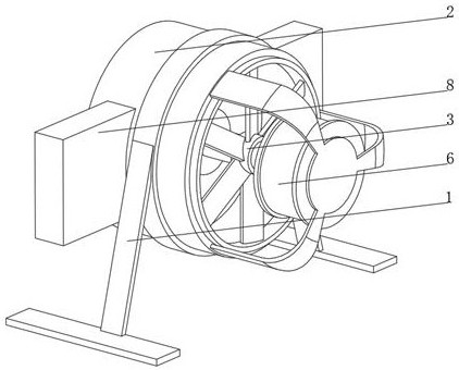
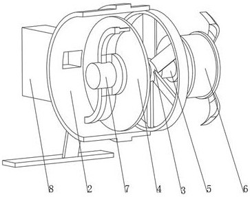
[0041] see Figure 1-3 , the present invention provides a technical solution: a smoke exhaust fan device, specifically comprising:
[0042] Fan casing 1, the bottom of the fan casing 1 is fixedly connected with a support frame 2, and one end of the inner wall of the fan casing 1 is rotatably connected with a rotating fan 3;
[0043] Filter 4, the filter 4 is arranged inside the fan housing 1 on the side of the rotating fan 3, the filter 4 runs through and is rotatably connected to the rotating shaft 5, one end of the rotating shaft 5 runs through the rotating fan 3 and is fixedly connected to the drive motor 6;
[0044] Cleaning device 7, this cleaning device 7 is arranged on one end away from drive motor 6 on rotating shaft 5, and cleaning device 7 is fixedly connected with rotating shaft 5;
[0045] Collecting device 8, the collecting device 8 is arranged on the part facing the cleaning device 7 on both sides of the fan casing 1, and one side of the collecting device 8 com...
Embodiment 2
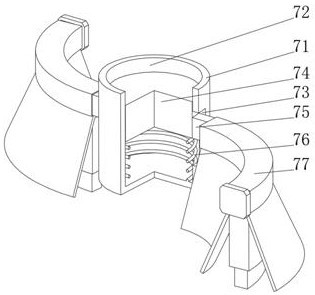
[0054] see Figure 1-4 On the basis of Embodiment 1, the present invention provides a technical solution: the brush head 77 includes a fixed sleeve 771, the bottom of the fixed sleeve 771 is fixedly connected with a brush plate 772, and the end of the brush plate 772 away from the fixed sleeve 771 is fixedly connected with a bristle 773, Both sides of the brush plate 772 are fixedly connected with inclined baffles 774, and the fixed sleeve 771 is sleeved on the connecting rod 75 and is slidably connected with the connecting rod 75. The shapes of the fixed sleeve 771 and the brush plate 772 are suitable for the shape of the connecting rod 75. Matching, the side of the bristle 773 away from the brush plate 772 is close to the surface of the filter screen 4 and is slidably connected with the filter screen 4. The length of the bristle 773 is 2-2.5 times the diameter of the inner mesh of the filter screen 4, and a brush head 77 is provided. When the comb head 77 was brushing on the...
Embodiment 3
[0056] see Figure 1-5 On the basis of Embodiment 1 and Embodiment 2, the present invention provides a technical solution: the collection device 8 includes a collection box 81, one end of the inner wall of the collection box 81 is fixedly connected with a push spring 82, and the push spring 82 is away from the inner wall of the collection box 81. One end is fixedly connected with a push plate 83, the side of the push plate 83 away from the collection box 81 is slidably connected with a storage box 84, one side of the storage box 84 is provided with a material opening 85, and the side of the storage box 84 above the material opening 85 is provided with a storage slot 86, the bottom of the inner wall of the storage tank 86 is fixedly connected with a storage spring 87, the end of the storage spring 87 away from the inner wall of the storage tank 86 is fixedly connected with an arc-shaped block 88, and the side of the storage box 84 away from the material opening 85 is provided wi...
PUM
 Abstract
Description
Claims
Application Information
 - R&D
- Intellectual Property
- Life Sciences
- Materials
- Tech Scout
- Unparalleled Data Quality
- Higher Quality Content
- 60% Fewer Hallucinations
Browse by: Latest US Patents, China's latest patents, Technical Efficacy Thesaurus, Application Domain, Technology Topic, Popular Technical Reports.
© 2025 PatSnap. All rights reserved.Legal|Privacy policy|Modern Slavery Act Transparency Statement|Sitemap|About US| Contact US: help@patsnap.com


