
High-efficiency flatness detection device for engineering survey

A detection device and flatness technology, applied in measurement devices, mechanical measurement devices, and mechanical devices, etc., can solve the problems of waste of manpower and material resources, low detection efficiency, limited detection area of ​​laser detection devices, etc., and achieve time reduction and rapid detection. Effect

Active Publication Date: 2022-05-17
浙江省工程物探勘察设计院有限公司
View PDF7 Cites 2 Cited by
  • Summary
  • Abstract
  • Description
  • Claims
  • Application Information

AI Technical Summary

Problems solved by technology

[0005] The purpose of the present invention is to provide a high-efficiency engineering survey flatness detection device to solve the above-mentioned background technology. When the prior art detects the flatness of the building construction ground, the laser detection device is generally used, but before the construction There will be a lot of sundries piled up on the ground or the ground in the construction work. During the detection process, the sundries will block the laser at the irradiation place of the laser detection device, thereby affecting the normal detection of the laser detection device. If the ground is cleaned, it will waste A lot of manpower and material resources, and it takes a long time, the detection efficiency is low, and the ground during construction will be poured with cement columns or support columns for the upper plate, which cannot be moved, which will affect the laser coverage of the laser detection device, thus affecting the laser detection device. The problem of limited detection area

Method used


Image

  • High-efficiency flatness detection device for engineering survey
  • High-efficiency flatness detection device for engineering survey
  • High-efficiency flatness detection device for engineering survey

Examples


Embodiment Construction

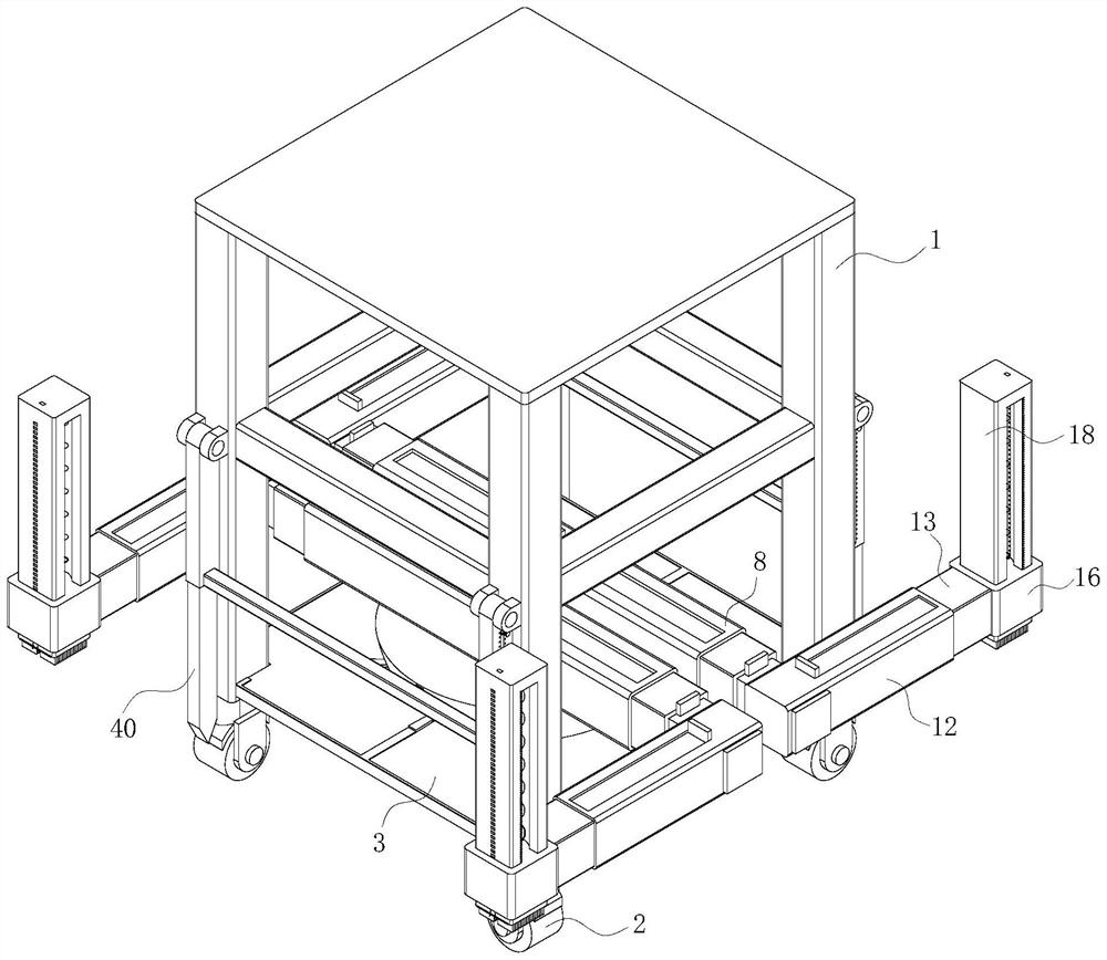
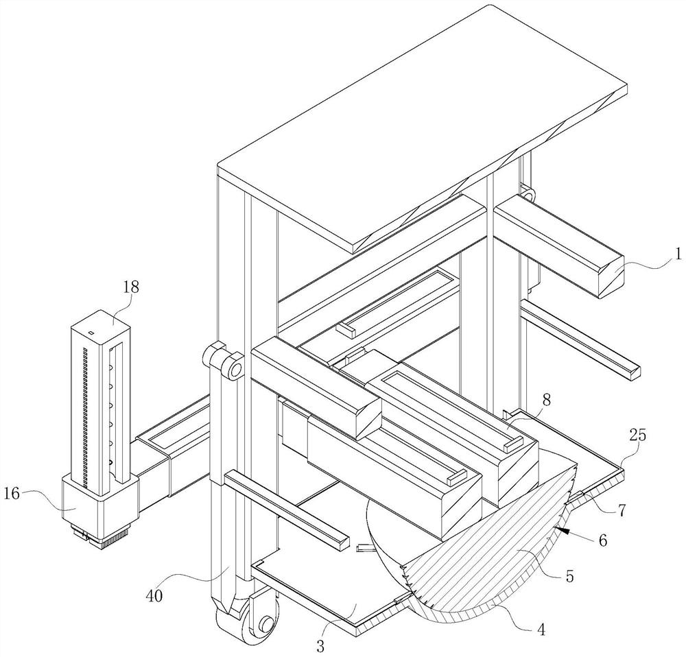
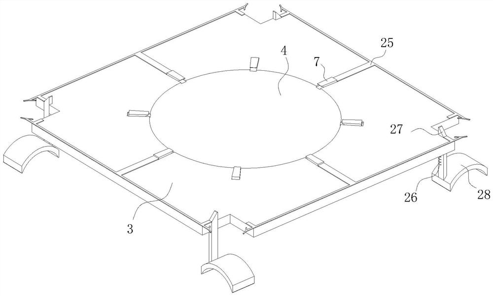
[0035] see Figure 1-15 , the present invention provides a technical solution: a flatness detection device for high-efficiency engineering survey, including a mounting frame 1, the four corners of the bottom of the mounting frame 1 are provided with rolling wheels 2, and the middle position of the mounting frame 1 is fixedly connected with a mounting Plate 3, the outside of mounting frame 1 is provided with a plurality of identical detection mechanisms, and the detection mechanism can detect the height of the construction ground at the positions of multiple detection mechanisms, and an adjustment mechanism is provided between the detection mechanism and the installation plate 3, and the adjustment mechanism can Adjust the position of the detection mechanism, the surface of the mounting plate 3 is provided with a horizontal mechanism that can keep the adjustment mechanism and the detection mechanism horizontal;

[0036] The horizontal mechanism includes an arc-shaped installati...


PUM


Abstract

The invention discloses a flatness detection device for high-efficiency engineering survey, and belongs to the technical field of flatness detection. The flatness detection device comprises a mounting frame, and rolling wheels are arranged at four corners of the bottom of the mounting frame; before detection, the horizontal block is limited firstly, so that the detection rods are all in a horizontal state during detection, and the situation that the detection rods are inclined due to inclination of the mounting frame and detected data are deviated, so that the detected data are large in deviation, and judgment of detection personnel on the ground flatness is affected is avoided; a plurality of points of the construction ground can be detected through a plurality of detection rods, the flatness condition of the construction ground can be obtained by counting and comparing the difference values of a plurality of read data, the flatness condition of the ground before construction can be quickly obtained, the detection positions of the detection rods only need to be cleaned, and the detection efficiency is greatly improved. The cleaning time is shortened, and rapid detection can be carried out.

Description

technical field [0001] The invention relates to the technical field of flatness detection, in particular to a flatness detection device for high-efficiency engineering survey. Background technique [0002] Engineering survey, on-the-spot survey and mapping work to find out the geological and geographical environment characteristics in the construction area and other natural conditions related to engineering construction, flatness detection is sometimes called frontal degree detection and coplanarity detection. In the process of highway and building construction, ensuring the flatness of construction is an important technical quality assurance. Use flatness testing equipment to collect data on the construction ground to detect the flatness of the construction ground. [0003] In the prior art, laser detection devices are generally used to detect the flatness of the building construction ground, but there are many sundries piled up on the ground before construction or on the g...

Claims


Application Information

Patent Timeline
Patent Type & Authority Applications(China)
IPC IPC(8): G01B5/02G01B5/28
CPCG01B5/02G01B5/28Y02E10/50
Inventor 叶洋帆赵志元顾运韬郑绍英徐涛
Owner 浙江省工程物探勘察设计院有限公司
Learn More