
Power distribution switch control equipment and control method

A technology for control equipment and power distribution switches, applied in substation/switch layout details, anti-seismic equipment, switchgear, etc.

Pending Publication Date: 2022-05-17
展铖科技(江苏)有限公司
View PDF0 Cites 0 Cited by
  • Summary
  • Abstract
  • Description
  • Claims
  • Application Information

AI Technical Summary

Problems solved by technology

[0003] Among them, the power distribution cabinet is divided into power distribution cabinet, lighting distribution cabinet and metering cabinet. It is the final equipment of the power distribution system. Load, and provide protection, monitoring and control for the load. When the existing power distribution cabinet is used in areas with more rainy seasons, the moisture content in the air is relatively high. When humid air enters the content of the power distribution cabinet, the moisture content reaches a certain level. It is easy to cause disconnection of electrical components, which affects the use of the power distribution cabinet, and in strong convective weather, when the water flow does not pass through the vent hole at the bottom of the power distribution cabinet, the power distribution cabinet cannot take corresponding protective measures, so a kind of protection is urgently needed Distribution switch control equipment and control method to solve the above problems

Method used


Image

  • Power distribution switch control equipment and control method
  • Power distribution switch control equipment and control method
  • Power distribution switch control equipment and control method

Examples


Embodiment Construction

[0026] The following will clearly and completely describe the technical solutions in the embodiments of the present invention with reference to the accompanying drawings in the embodiments of the present invention. Obviously, the described embodiments are only some, not all, embodiments of the present invention. Based on the embodiments of the present invention, all other embodiments obtained by persons of ordinary skill in the art without making creative efforts belong to the protection scope of the present invention.

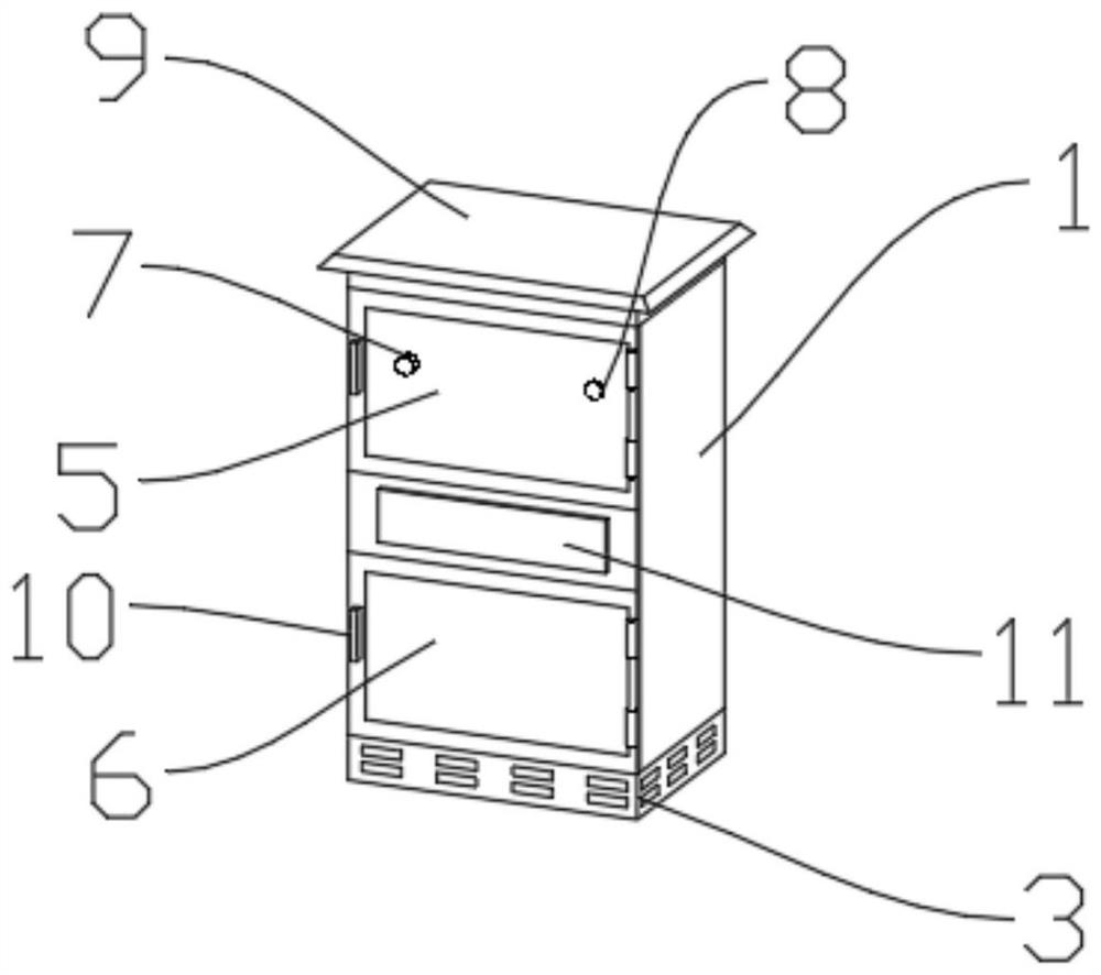
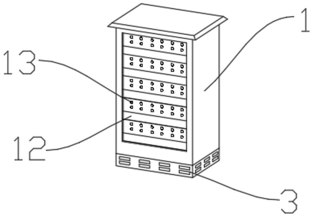
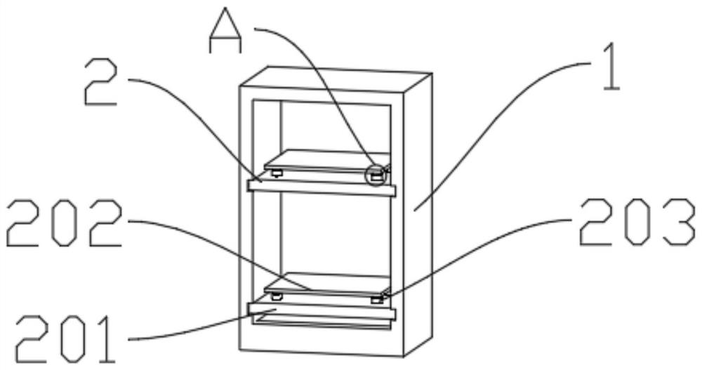
[0027] see Figure 1-6 , the figure shows a power distribution switch control device of the present invention, including a device main body 1, a shock absorbing assembly 2, a waterproof unit 3, and a hot air unit 4, and the shock absorbing assembly 2 includes a pumping plate 201, a bearing plate 202, and a buffer unit 203, and The pumping plate 201 is slidably connected to the main body 1 of the device, and the carrying plate 202 is flexibly connected to the p...


PUM


Abstract

The invention relates to the technical field of power distribution switch control equipment, in particular to power distribution switch control equipment and a control method.The power distribution switch control equipment comprises an equipment body, a damping assembly, a waterproof unit and a hot air unit, the damping assembly comprises a pulling plate, a bearing plate and a buffering unit, and the pulling plate is slidably connected with the equipment body; the bearing plate is movably connected with the pulling plate through a plurality of buffer units, the waterproof unit comprises a bottom plate, a baffle and electromagnetic switches, the bottom end of the baffle is connected to the top end of the bottom plate in a sleeving mode and clamped through a plurality of electromagnetic switches, a plurality of air holes are formed in the bottom plate in the perimeter direction, and a plurality of hot air blowers are arranged in the hot air unit. The bottom end of the hot air unit is fixedly connected with the bottom end of the bottom plate, different humidity threshold values are set for the two humidity sensors, and when the humidity sensor B transmits signals to the central processing unit, the central processing unit controls the emergency warning lamp to conduct an emergency warning function and prompts related workers to conduct the maintenance process on the device.

Description

technical field [0001] The invention relates to the technical field of power distribution switch control equipment, in particular to a power distribution switch control device and a control method. Background technique [0002] Power distribution is a link in the power system that is directly connected to users and distributes electric energy to users. The power distribution system is mainly composed of power distribution substations, high-voltage distribution lines, distribution transformers, low-voltage power distribution lines and corresponding control and protection equipment. Among them, the power distribution switch control equipment is one of the control and protection equipment, which plays a vital role in the on-off control of the circuit. There are many kinds of power distribution switch control equipment on the market, which are divided into primary equipment and secondary equipment. Equipment, primary equipment is the equipment that directly generates, transmits,...

Claims


Application Information

Patent Timeline
IPC IPC(8): H02B1/54H02B1/56H02B1/28H02B1/20H02B1/36H02B11/127H02J13/00
CPCH02B1/54H02B1/565H02B1/28H02B1/20H02B1/36H02B11/127H02J13/00002
Inventor 于奎顾小勇
Owner 展铖科技(江苏)有限公司
Learn More