
Anti-maloperation device for interface of optical transmission equipment

A device interface and anti-misoperation technology, which is applied in the field of optical fiber equipment, can solve the problems that cannot prevent staff from negligently misoperating and pulling out optical fibers, and achieve the effect of preventing human errors and improving reliability

Active Publication Date: 2022-05-17
MAINTENANCE BRANCH OF STATE GRID HEBEI ELECTRIC POWER +1
View PDF7 Cites 0 Cited by
  • Summary
  • Abstract
  • Description
  • Claims
  • Application Information

AI Technical Summary

Problems solved by technology

[0009] The invention provides an anti-misoperation device for the interface of optical transmission equipment, which is used to solve the problem in the prior art that it cannot prevent the staff from negligently operating and misoperating to pull out the optical fiber

Method used


Image

  • Anti-maloperation device for interface of optical transmission equipment
  • Anti-maloperation device for interface of optical transmission equipment
  • Anti-maloperation device for interface of optical transmission equipment

Examples


Embodiment 1

[0059] In the prior art, prompts are usually used for misoperations caused by personnel errors, but in some cases, there is still a certain risk of misoperations, and only when the misoperations are completely prevented can it play a preventive role.

[0060] Therefore, the embodiment of the present invention provides a device with a locking mechanism, which is similar to an interface panel, which can be used in new production equipment, and can also be used for technical transformation of existing equipment.

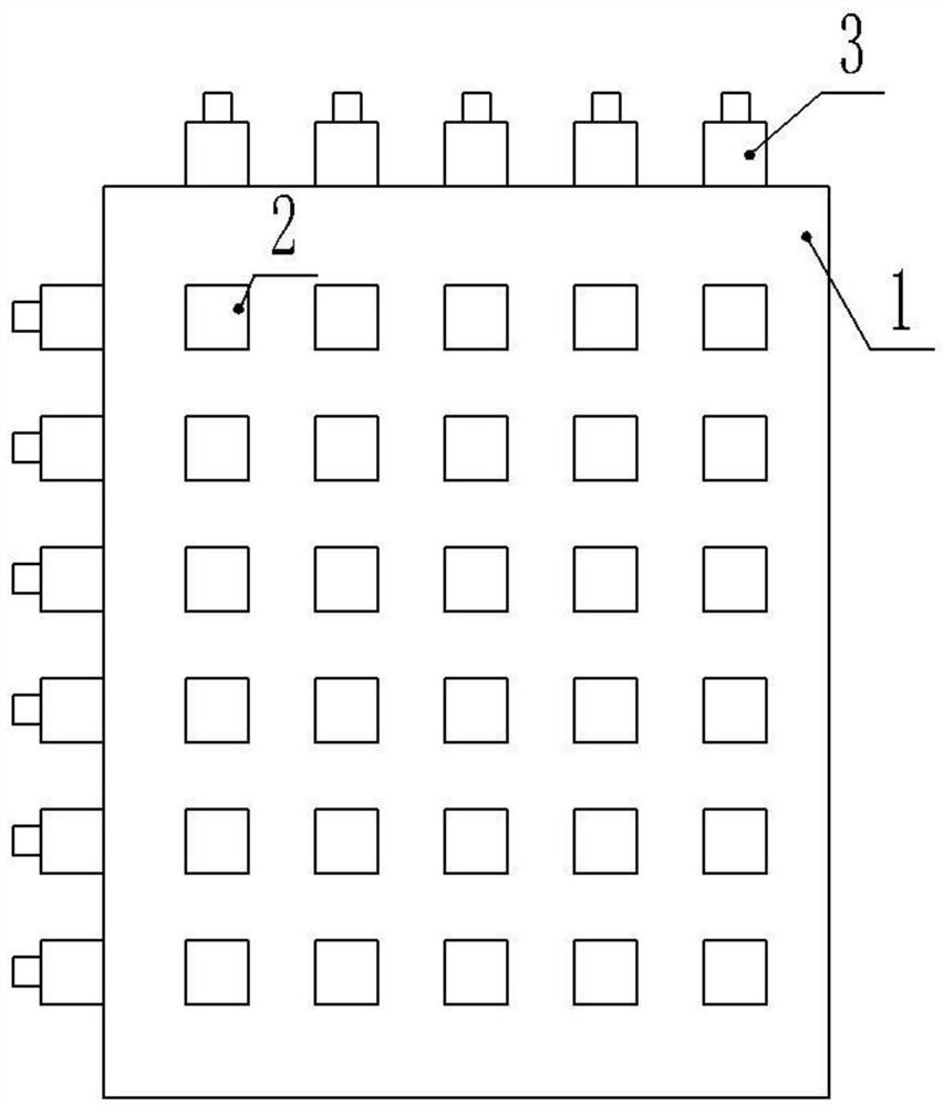
[0061] The body frame 1 is a plate-shaped object, and its surface is provided with a plurality of openings 2 . In one embodiment, the openings 2 are through holes, and the shape of the openings 2 is adapted to the connector 5 of the optical fiber. The openings 2 are arranged regularly. In one application scenario, there are M rows and N columns. Both M and N are positive integers greater than 1. Therefore, the body frame 1 is provided with M×N openings 2 in total.

[00...

Embodiment 2

[0078] This embodiment includes all the technical solutions of the first embodiment, and is a further expansion on the technical solution of the first embodiment.

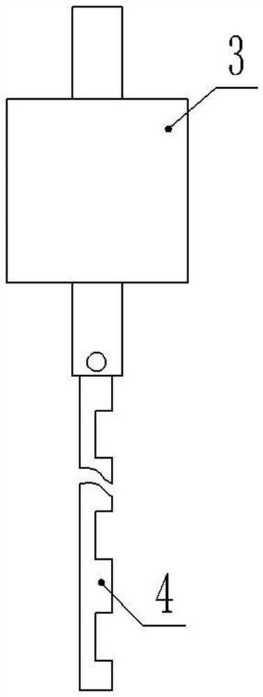
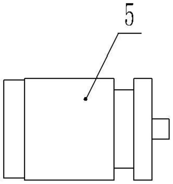
[0079] In some technical solutions, a joint 5 adapted to the opening 2 is also provided, and the joint 5 is clearance-fitted with the opening 2, that is, when the two latches are in an open state (that is, when the opening 2 is fully exposed), the joint 5 The opening 2 can be passed freely in and out. At least two sides of the joint 5 are provided with grooves, and these two grooves are adapted to the dead bolts of the lock. When the dead bolts stretch out, they just block the grooves of the joint 5 so that the joint 5 cannot move.

[0080] In a common implementation, the cross section of the joint 5 is square, and the overall shape is a cylinder, and an annular groove is provided on the side of the cylinder, so as to realize the first side and the second side in the above description. slot effect.

[0081] As we...

Embodiment 3

[0091] Embodiment 3: This embodiment includes all technical solutions of Embodiment 2, and is a further improvement based on Technical Solution 2.

[0092] There is an indicator light next to each opening 2, which can be controlled by the control device to achieve the effect of indicating the state of the opening 2, such as when the optical fiber in the Mth row and Nth column needs to be pulled out, it is located in the Mth row The indicator light in the Nth column is on, which can achieve the effect of quickly finding the corresponding optical fiber through prompts.

[0093] There are various ways to turn on and off the indicator light.

[0094] One of the ways is that two position switches are arranged between the indicator light and the power supply, and the two position switches are connected in series with the indicator light. Therefore, only when the two position switches are all closed, the indicator light is on. The moving ends of the two position switches are set at ...


PUM


Abstract

The invention discloses an optical transmission equipment interface anti-misoperation device, and relates to the technical field of optical fiber equipment, in particular to an optical transmission equipment interface anti-misoperation device, which comprises a body frame, a first clamping lock and a second clamping lock, the body frame is provided with a plurality of openings, the openings are arranged in a multi-row and multi-column mode, the first clamping lock and the second clamping lock are respectively provided with a spring bolt, the spring bolts are provided with notches, when the spring bolts stretch out or retract, the notches and the openings are driven to be aligned or staggered, and when the spring bolts are staggered, the spring bolts clamp optical fibers and limit the positions of the optical fibers, so that the optical fibers cannot move. The number of the first clamping locks and the number of the second clamping locks correspond to the number of the rows and the number of the columns of the multiple openings respectively, the first clamping locks and the second clamping locks are arranged in the other two different directions of the body frame respectively, and the two portions, inserted into the openings, of the optical fibers are clamped through the corresponding spring bolts of the first clamping locks and the second clamping locks. When any opening needs to be unlocked, only the clamping locks in the row where the opening is located and the two clamping locks in the column where the opening is located need to be unlocked.

Description

technical field [0001] The invention relates to the technical field of optical fiber equipment, in particular to an anti-misoperation device for an interface of optical transmission equipment. Background technique [0002] Optical transmission equipment refers to equipment that converts various signals into optical signals and transmits them on optical fibers. It is an important transmission equipment in the power communication optical transmission system. It is mainly used for photoelectric conversion, signal transmission and processing, and is widely used in many industries such as telecommunications, electric power, monitoring, and industrial control. The optical transmission equipment is provided with an optical fiber interface, which is used to connect a physical interface of an optical fiber cable. [0003] In the prior art, there is no anti-malfunction device applied to the optical fiber interface of the optical transmission equipment. The optical transmission equip...

Claims


Application Information

Patent Timeline
Patent Type & Authority Applications(China)
IPC IPC(8): H04B10/25H04B10/073G07C9/00H04M1/72415
CPCH04B10/25H04B10/0731G07C9/00309H04M1/72415
Inventor 梁雪峰段志勇赵新睿李志伟袁冰王守豪王旭晖尹灵珊
Owner MAINTENANCE BRANCH OF STATE GRID HEBEI ELECTRIC POWER
Learn More