Rotatable umbrella

A rotating and umbrella technology, applied in umbrellas, travel products, clothing, etc., can solve the problems of inconvenience, non-rotation, trouble, etc., and achieve the effect of increasing applicability and increasing area

Pending Publication Date: 2022-05-20
NINGBO MIDEAY ELECTRICAL APPLICANCE CO LTD
View PDF0 Cites 0 Cited by
  • Summary
  • Abstract
  • Description
  • Claims
  • Application Information

AI Technical Summary

Problems solved by technology

[0002] Umbrellas include umbrella handles, umbrella poles, umbrella surfaces and other auxiliary devices. The umbrella handle is fixed at the lower end of the umbrella pole and cannot be rotated. If you want to rotate the umbrella, you can only use it to rotate the whole umbrella by twisting the handle or umbrella pole. trouble
In addition, if you use it in a windy situation, the wind will blow the umbrella to generate torsion, and the torsion will act between the umbrella handle and your hand. Inconvenient to use
[0003] Existing rotating umbrellas realize rotation by installing a rotating mechanism on the umbrella pole, installing a bearing at the junction of the umbrella handle and the umbrella pole, and installing a turntable on the umbrella rib, etc., but the existing rotating umbrella only has a rotation mode. Doesn't fit and still spins, and there's no way to switch between a normal umbrella and a spinning umbrella

Method used


Image

  • Rotatable umbrella
  • Rotatable umbrella
  • Rotatable umbrella

Examples


Embodiment Construction

[0046] In order to make the purpose, technical solutions and advantages of the embodiments of the present invention more clear, the technical solutions in the embodiments will be clearly and completely described below in conjunction with the drawings in the embodiments of the present invention. The following embodiments are used to illustrate the present invention , but not to limit the scope of the present invention.

[0047] In the description of the present invention, it should be noted that the terms "upper", "lower", "front", "rear", "left", "right", "vertical", "inner", "outer" etc. The indicated orientation or positional relationship is based on the orientation or positional relationship shown in the drawings, and is only for the convenience of describing the present invention and simplifying the description, rather than indicating or implying that the referred device or element must have a specific orientation, or in a specific orientation. construction and operation, ...


PUM


Abstract

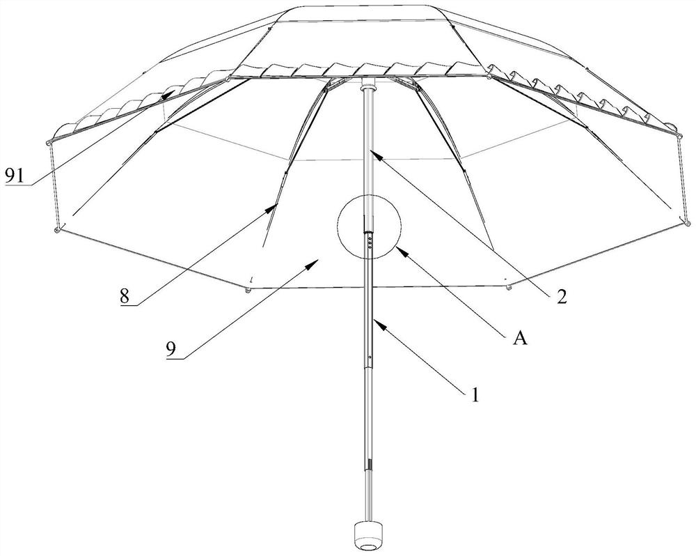
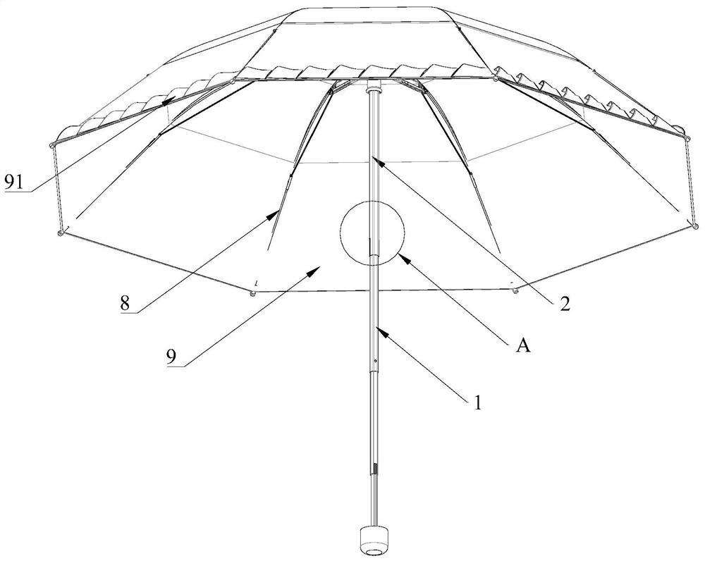
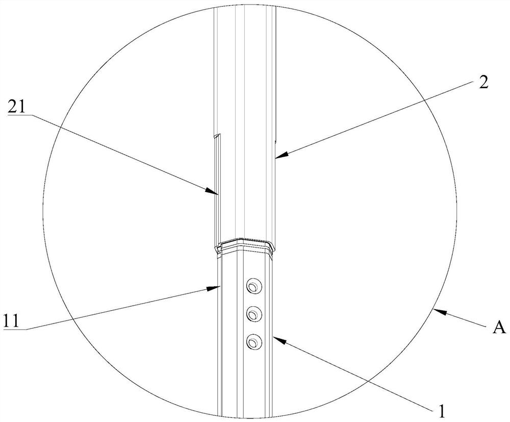
The invention discloses a rotatable umbrella which comprises a first connecting rod, a second connecting rod and a rotating shaft. The first connecting rod and the second connecting rod are connected through a rotating shaft, the rotating shaft is sleeved with the second connecting rod, the second connecting rod is movably arranged in the axial direction of the rotating shaft, and the first connecting rod and the second connecting rod have two states: the first state is that the second connecting rod is sleeved with the first connecting rod, and the second connecting rod is movably arranged in the axial direction of the rotating shaft; the first connecting rod and the second connecting rod integrally rotate in the circumferential direction; and in the second state, the second connecting rod is separated from the first connecting rod in a sleeving manner and can rotate relative to the first connecting rod in the circumferential direction. When in the first state, the umbrella is a common umbrella and cannot rotate; and when the umbrella is in the second state, the umbrella is a rotatable umbrella, so that the wind resistance during advancing is reduced, the ornamental value and the entertainment value are enhanced, the umbrella can be switched between the two modes, and the applicability of the umbrella is improved.

Description

technical field [0001] The invention belongs to the field of umbrellas, in particular to a rotatable umbrella. Background technique [0002] Umbrellas include umbrella handles, umbrella poles, umbrella surfaces and other auxiliary devices. The umbrella handle is fixed at the lower end of the umbrella pole and cannot be rotated. If you want to rotate the umbrella, you can only use it to rotate the whole umbrella by twisting the handle or umbrella pole. trouble. In addition, if you use it in a windy situation, the wind will blow the umbrella to generate torsion, and the torsion will act between the umbrella handle and your hand. Inconvenient to use. [0003] Existing rotating umbrellas realize rotation by installing a rotating mechanism on the umbrella pole, installing a bearing at the junction of the umbrella handle and the umbrella pole, and installing a turntable on the umbrella rib, etc., but the existing rotating umbrella only has a rotation mode. If it doesn't fit, it...

Claims


Application Information

Patent Timeline
Patent Type & Authority Applications(China)
IPC IPC(8): A45B11/00A45B25/22A45B25/02A45B25/18
CPCA45B11/00A45B25/22A45B25/02A45B25/18A45B2011/005
Inventor 孙利云胡小亮
Owner NINGBO MIDEAY ELECTRICAL APPLICANCE CO LTD
Why Eureka
Try Eureka