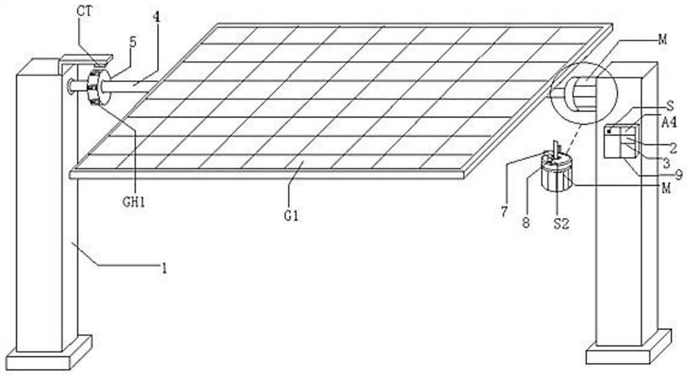
Photovoltaic module support frame and photovoltaic module system

A photovoltaic module and support frame technology, which is applied to the support structure of photovoltaic modules, photovoltaic modules, photovoltaic power generation and other directions, can solve the problems of inability for users to operate, high cost, complex structure, etc., to achieve low cost, high power generation capacity, Simple and compact structure

Pending Publication Date: 2022-05-20
万桂英
View PDF0 Cites 0 Cited by
  • Summary
  • Abstract
  • Description
  • Claims
  • Application Information

AI Technical Summary

Problems solved by technology

[0004] In order to overcome the existing solar irradiation angle adjustment system used in relatively large photovoltaic generator sets, due to the limitation of the structure, there are disadvantages of complex structure and high cost, and because its internal control program is a fixed mode, when changing its internal control program Professional technicians are required to operate, and ordinary users cannot operate. The invention provides a simple and compact structure and low cost, and is especially suitable for the use of low-power photovoltaic generator sets. Under the joint action of related mechanisms and circuits, the user It can be easily adjusted and controlled. The motor deceleration mechanism drives the solar panel to rotate at a certain angle to receive strong light at a certain time interval every day, and the remote user can also understand the working status of the equipment in real time, and can adjust the remote solar panel through the mobile phone if necessary. In the direction of the sun (for example, the weather changes suddenly and turns sunny, the original automatic control mode cannot guarantee the power generation effect of the solar panel against the sun), thus ensuring the high power generation capacity of the solar panel as much as possible. A photovoltaic module support frame and photovoltaic module system

Method used


Image

  • Photovoltaic module support frame and photovoltaic module system
  • Photovoltaic module support frame and photovoltaic module system

Examples


Embodiment Construction

[0016] figure 1 , 2 As shown, a photovoltaic module support frame and a photovoltaic module system include a support frame 1, a motor deceleration mechanism M, a short message module A4, a power switch S, and a solar panel G1, and also have a detection mechanism, a time control circuit 2, and a remote control circuit 3. There are two sets of support frames 1, and the two sets of support frames 1 are respectively installed on both sides of the ground through screw nuts. There is a connecting shaft 4 in the middle of both sides of the solar panel G1 (photovoltaic module), and a connecting shaft 4 at the left end. The tight sleeve on the left side of the left end support frame 1 is installed in the bearing inner ring of the upper middle bearing seat 101 on the inner side of the left end support frame 1. The power output shaft of the motor reduction mechanism M and the right side of the connecting shaft 4 on the right side are connected together by a screw nut through a flange, an...


PUM


Abstract

The photovoltaic module support frame comprises a support frame, a motor speed reducing mechanism, a short message module, a solar cell panel, a detection mechanism, a time control circuit and a remote control circuit, a connecting shaft at one end of the solar cell panel is rotationally installed at the upper end of one supporting frame, a power output shaft of a motor speed reducing mechanism and the connecting shaft at the other end are installed together, and the motor speed reducing mechanism is installed at the upper end of the other supporting frame. The detection mechanism comprises a plurality of reed switches, a shell and a magnet, the shell is installed on the outer side of the connecting shaft at one end, the reed switches are installed in the fixing holes respectively, and the magnet is installed at the upper end of one supporting frame; and the short message module, the time control circuit and the remote control circuit are arranged in the electric cabinet and are electrically connected with the reed switch and the motor reducing mechanism. The solar cell panel can be automatically or manually controlled to automatically adjust the angle, and the high power generation capacity of the solar cell panel is guaranteed as much as possible. On the basis, the method has a good application prospect.

Description

technical field [0001] The invention relates to the technical field of solar power generation auxiliary equipment, in particular to a photovoltaic module support frame and a photovoltaic module system. Background technique [0002] Solar panels (photovoltaic modules) have been widely used due to energy saving and environmental protection. Existing solar panels are generally installed in a fixed state, that is to say, their light-receiving surface is in a fixed state. Since the illumination angle of an area is not constant, the solar panels installed in the fixed mode will be damaged when the sunlight deviates from its light-receiving surface. It will cause the power generation capacity to decline, and accordingly the good power generation effect cannot be achieved. [0003] Although in the existing technology, there is also a sunlight angle adjustment system, which ensures that the solar panel can receive sufficient sunlight and emit relatively high power according to the s...

Claims


Application Information

Patent Timeline
IPC IPC(8): H02S20/30H02S20/32H04W4/14
CPCH02S20/30H02S20/32H04W4/14Y02E10/50
Inventor万桂英
Owner万桂英