Automatic control puncture positioner for patient with cardiac effusion in department of cardiology
A technology of cardiology and locator, applied in the fields of puncture needle, medical science, surgery, etc., can solve the problems of inability to synchronously understand the use status of the puncture needle, unable to move the puncture needle to the designated position, and reducing the accuracy of acupuncture, so as to improve the success rate of surgery. , Improve the comfort of connection and the effect of convenient control and operation
- Summary
- Abstract
- Description
- Claims
- Application Information
AI Technical Summary
Problems solved by technology
Method used
Image
Examples
Embodiment 1
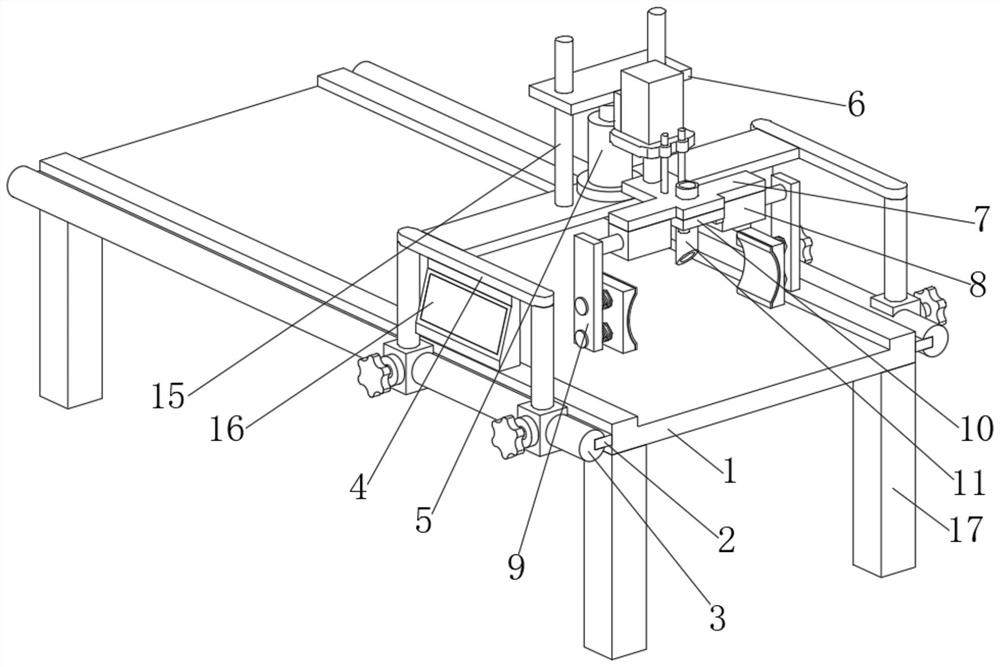
[0035] An automatic control puncture locator for patients with cardiac effusion in cardiology department, such as Figure 1-3As shown, it includes a bed frame 1, the front and rear ends of the bed frame 1 are fixedly connected with clips 2, and two clips 2 are clipped and fixed with a sliding column 3, and the two sliding columns 3 are jointly slidably connected with a movable Mechanism 4, the middle of the upper end of the moving mechanism 4 is fixedly connected with a No. 1 electric push rod 5, and the output end of the No. 1 electric push rod 5 is fixedly connected with a lifting plate 6, and the front and rear of the lifting plate 6 are interspersed and movably connected with a No. 1 guide. Column 15, the lower ends of the two No. 1 guide columns 15 are fixedly connected with the upper end of the moving mechanism 4, and the middle part of the right end of the lifting plate 6 is fixedly connected with an adjustment mechanism 7, the adjustment mechanism 7 is L-shaped as a who...
Embodiment 2
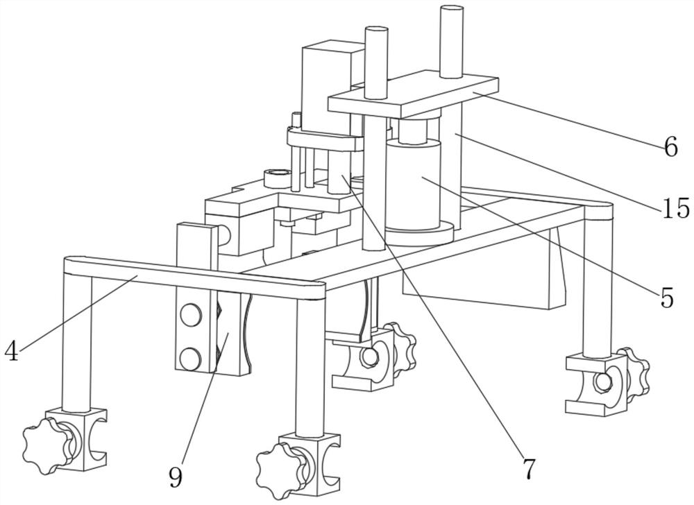
[0042] On the basis of Example 1, as Figure 4-5 As shown, an automatic control puncture locator for patients with cardiac effusion in the department of cardiology includes a bed frame 1, the front and rear ends of the bed frame 1 are fixedly connected with clips 2, and two clips 2 are clipped and fixed with sliding Column 3, a moving mechanism 4 is slidably connected to the two sliding columns 3. The upper middle of the moving mechanism 4 is fixedly connected with a No. 1 electric push rod 5, and the output end of the No. 1 electric push rod 5 is fixedly connected with a lifting plate 6. The front part and the rear part of the 6 are interspersed and movably connected with a No. 1 guide post 15, the lower ends of the two No. 1 guide posts 15 are fixedly connected with the upper end of the moving mechanism 4, and the middle part of the right end of the lifting plate 6 is fixedly connected with an adjusting mechanism 7. The mechanism 7 is L-shaped as a whole, a block 10 is fixed...
Embodiment 3
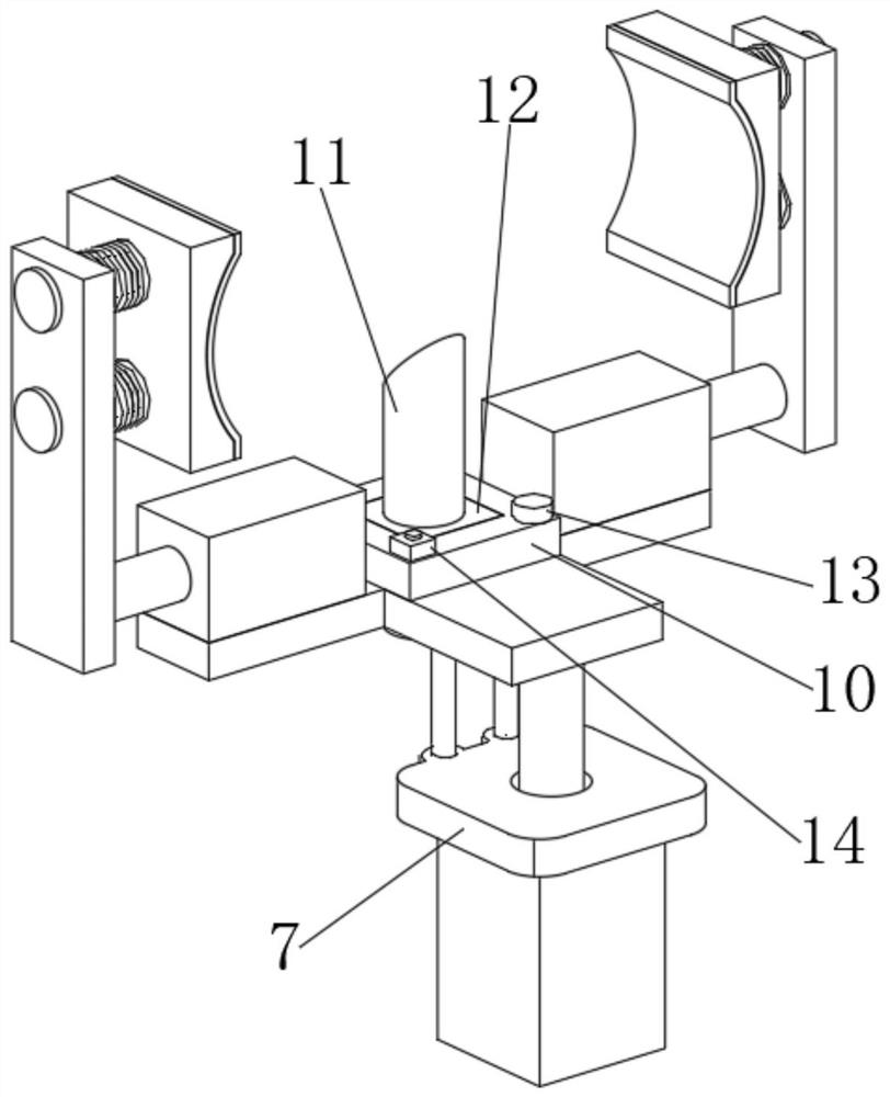
[0051] On the basis of Example 1, as Figure 6-7 As shown, an automatic control puncture locator for patients with cardiac effusion in the department of cardiology includes a bed frame 1, the front and rear ends of the bed frame 1 are fixedly connected with clips 2, and two clips 2 are clipped and fixed with sliding Column 3, a moving mechanism 4 is slidably connected to the two sliding columns 3. The upper middle of the moving mechanism 4 is fixedly connected with a No. 1 electric push rod 5, and the output end of the No. 1 electric push rod 5 is fixedly connected with a lifting plate 6. The front part and the rear part of the 6 are interspersed and movably connected with a No. 1 guide post 15, the lower ends of the two No. 1 guide posts 15 are fixedly connected with the upper end of the moving mechanism 4, and the middle part of the right end of the lifting plate 6 is fixedly connected with an adjusting mechanism 7. The mechanism 7 is L-shaped as a whole, a block 10 is fixed...
PUM
 Abstract
Description
Claims
Application Information
 - R&D
- Intellectual Property
- Life Sciences
- Materials
- Tech Scout
- Unparalleled Data Quality
- Higher Quality Content
- 60% Fewer Hallucinations
Browse by: Latest US Patents, China's latest patents, Technical Efficacy Thesaurus, Application Domain, Technology Topic, Popular Technical Reports.
© 2025 PatSnap. All rights reserved.Legal|Privacy policy|Modern Slavery Act Transparency Statement|Sitemap|About US| Contact US: help@patsnap.com


