
Injection mold with umbrella-shaped cooling water channel

A cooling waterway and injection mold technology, applied in the field of molds, can solve the problems of poor cooling effect, increased cost, small contact area of ​​cooling surface, etc., and achieve the effect of improving structural strength and reducing production difficulty

Pending Publication Date: 2022-05-24
浙江西诺模具有限公司
View PDF6 Cites 0 Cited by
  • Summary
  • Abstract
  • Description
  • Claims
  • Application Information

AI Technical Summary

Problems solved by technology

In the existing technical solutions, the cooling of the finished product by the water channel of the mold is not uniform enough during operation, or the design of the water channel is too complicated for the purpose of uniform cooling
[0003] For example, the "mold insert with inclined alternating waterway structure and its manufacturing method" disclosed in the Chinese patent literature, its notification number is CN102909841B, includes an insert, and the insert has a conical section with a circular bottom surface, and its outer wall is Conical surface, with multiple sets of inclined alternating waterway structures inside. Each set of inclined alternating waterway structures includes left inclined waterway and right inclined waterway. The waterways penetrate from the circular bottom surface of the insert and extend straight upward to intersect with the insert. Inside, the angle between the axis of the left inclined waterway and the circular bottom surface is equal to the angle between the axis of the right inclined waterway and the circular bottom surface, and multiple sets of inclined alternating waterway structures are evenly distributed along the same circumference. In the insert, when the mold insert is used to produce a cylindrical cup-shaped transparent plastic product, the cooling effect of the upper and lower parts of the product can be relatively balanced. The cooling effect of the segment is worse than that of the previous segment, and there are still defects in the balance of the cooling effect
[0004] When this type of mold is cooling, different parts have different cooling requirements. The best cooling effect is often required near the glue inlet. The entire cooling channel often needs to use materials that are good for heat dissipation, such as beryllium copper. Therefore, the cost is greatly increased.
[0005] For example, the "metal mold insert containing a new waterway structure" disclosed in the Chinese patent literature, its notification number is CN211074367U, includes an insert, and at least one cavity is arranged in the insert, and the insert is erected in the cavity The mold cavity, the outer wall of the insert mold cavity and the inner wall of the cavity are arranged at intervals, and the annular space between the insert mold cavity and the cavity constitutes a cooling channel cavity, which overcomes the small contact area of ​​the cooling surface and the cooling effect existing in the prior art. The problem of uneven effect and low cooling efficiency, and the mold insert is made of metal to further improve the cooling effect, but because the entire mold insert is made of metal, the manufacturing cost is increased

Method used


Image

  • Injection mold with umbrella-shaped cooling water channel
  • Injection mold with umbrella-shaped cooling water channel
  • Injection mold with umbrella-shaped cooling water channel

Examples


Embodiment 1

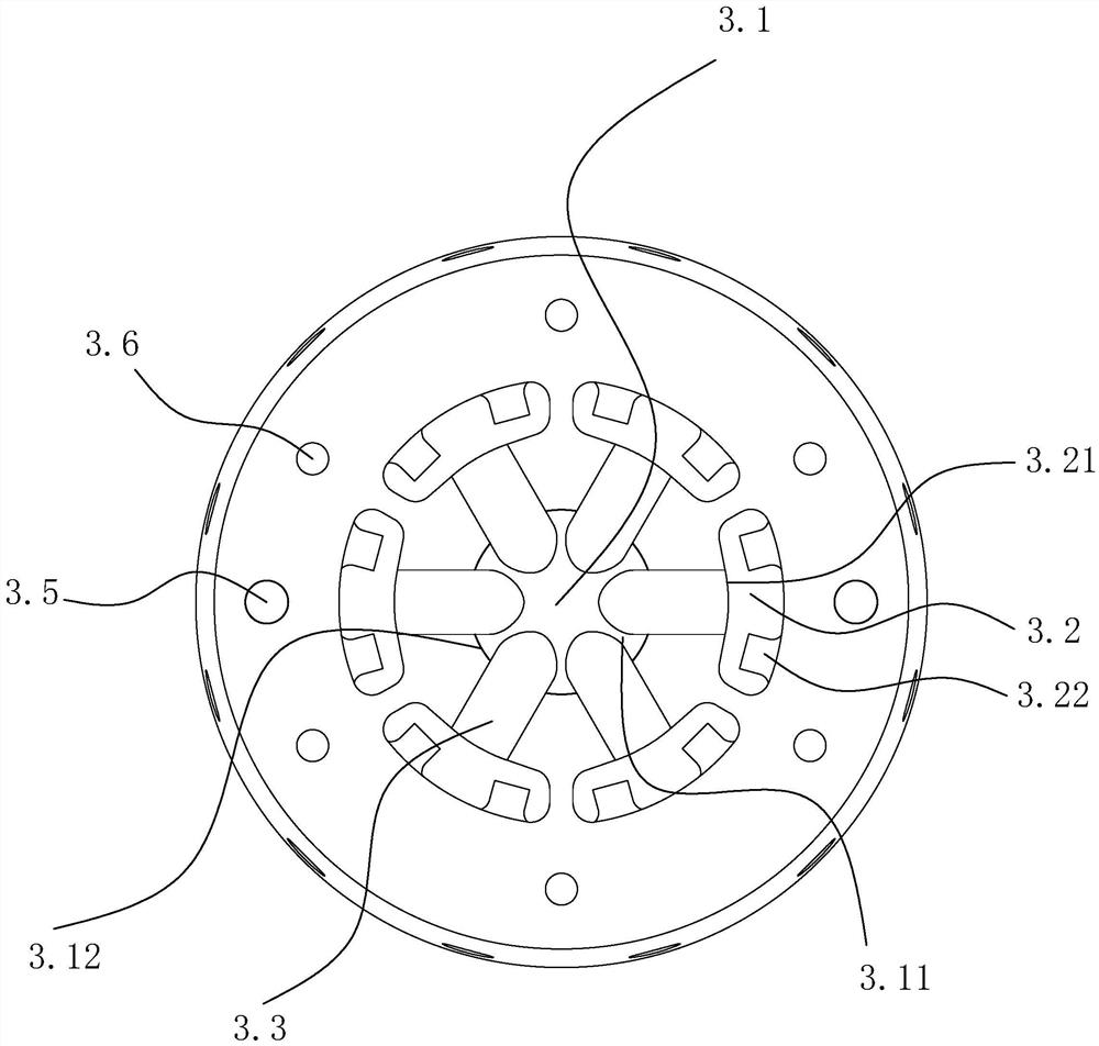
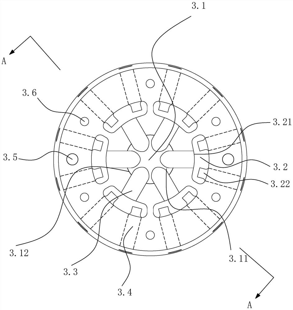
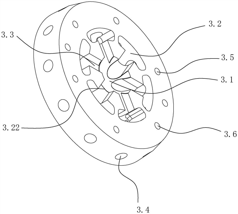
[0035] Example one, e.g., Figure 1 and Figure 2 As shown, an injection mold with an umbrella-like cooling waterway, including the mold body 1, the mold base 2 and the insert 3, the insert 3 is made of beryllium copper material, the mold body is a small and large round table shape, set in the center above the mold base, the insert is round cake-like, The middle is provided with a guide tank 3.1, the guide tank is an upwardly raised semicircle; the two branch pipes 3.2, the two branch pipes are provided with six identical to each other, with the guide tank 3.1 as the center of the uniform distribution in the direction of the circumference, each two branch pipe 2 is provided with an inlet 3.21 towards the guide sink 3.1 and the outlet of the two back guide sinks 3.22; the first branch 3 ends are connected to the inlet 3.1 of the two branch pipes 3.21, a total of six, all uniformly distributed along the radial direction of the same circumference; the second branch 3.4 is provided with...

Embodiment 2

[0042] Example TWO, e.g., Figure 5 As shown, the insert is uniformly provided along the circumference of eight two branch pipes 3.2, eight first branches and sixteen second branches, other settings are the same as Example I, the increased second branch may make the cooling channel more densely distributed, improve the cooling efficiency.

Embodiment 3

[0043] Example THREE, e.g., Figure 6As shown, on the basis of Example 1, the mount surface is provided with an inlet in the middle of the other side of the sink, The water control tank is set in a spherical water control 3.7, the top of the water control ball and the top of the inner wall of the water guide tank 1 are connected by a connecting line, the water control ball is evenly distributed around the six temperature sensing components, the temperature sensing component is connected to the control water ball and the channel wall of the water guide, when it is not working, the thermostat is maintained in the water guide through the connecting line, when the working state, the temperature sensor component with the surrounding temperature change produces obvious expansion and contraction, when due to the speed of raw material flow to each runner or the flow rate is uneven or other factors, resulting in uneven heat in each direction of the glue inlet and the main body of the mold, ...


PUM


Abstract

The injection mold comprises a mold body, a mold base and inserts, the mold body is arranged in the center of the upper portion of the mold base, and the inserts comprise the insert, the umbrella-shaped cooling water channel, the umbrella-shaped cooling water channel and the umbrella-shaped cooling water channel. The water chute is positioned in the middle; the two branch pipes are uniformly distributed along the circumferential direction and are provided with an inward inlet and two outward outlets; the two ends of the first branches are connected with the water guide groove and the inlets of the two branch pipes respectively, and the first branches are evenly distributed in the radial direction of the same circumference; one end of the second branch is connected with the outlets of the two branch pipes, and the other end of the second branch extends outwards to the outer part of the insert and is uniformly distributed along the radial direction of the same circumference; and the mold main body is internally provided with an insert groove and a cooling water channel which correspond to the insert. Through the design of the umbrella-shaped water channels, the cooling water channels are evenly distributed in the circumferential direction, the cooling effect can be truly balanced, meanwhile, due to the fact that the insert and the mold can be separated, the insert and the mold can be made of materials with different heat-conducting properties, and cost is saved.

Description

Technical field [0001] The present invention relates to the field of molds, in particular to an injection mold with an insert having an umbrella-like cooling circuit. Background [0002] In the injection mold, the cooling system is its core part, which has an important impact on the life of the mold, the production efficiency and quality of the injection molded products. The influence of waterways on the quality of molded products is mainly manifested in the product molding, which is used to control the mold temperature, and the change of mold temperature has an impact on the shrinkage deformation, dimensional stability, mechanical strength, stress cracking and surface quality of the product. In the existing technical solution, the waterway of the mold is not uniform enough to cool the finished product during work, or the waterway design is too complicated in order to achieve the purpose of uniform cooling. [0003] For example, the "mold insert with an inclined alternating water...

Claims


Application Information

Patent Timeline
Patent Type & Authority Applications(China)
IPC IPC(8): B29C45/73
CPCB29C45/7312
Inventor 李君章金宇林政林娅丹
Owner 浙江西诺模具有限公司
Learn More