Auxiliary tool for welding forming of machine tool protective cover

A technology of welding forming and auxiliary tooling, which is applied in the direction of welding/cutting auxiliary equipment, auxiliary devices, welding equipment, etc., can solve the problems of affecting welding operation, manpower consumption, and cumbersome docking operation process, so as to ensure the quality of welding processing and improve work efficiency. Efficiency and the effect of reducing manpower consumption

Inactive Publication Date: 2022-05-27
徐州玖维轩电子科技有限公司
View PDF0 Cites 0 Cited by
  • Summary
  • Abstract
  • Description
  • Claims
  • Application Information

AI Technical Summary

Problems solved by technology

[0004] However, at present, there are mainly the following problems in the welding process of machine tool shields: First, the shield and the limit plate are often connected to the limit plate and the shield by manual marking, which is inaccurate and relatively stable during the docking process. Poor, which affects the welding operation, and the docking operation process is cumbersome, which affects the processing efficiency; secondly, during the welding process, it is necessary to manually turn over the welding dead corner of the shield, which consumes manpower and affects the processing efficiency; thirdly, the rotation angle of the manual rotation shield is limited , the corner welding operation is inconvenient, which affects the welding quality at the corner

Method used


Image

  • Auxiliary tool for welding forming of machine tool protective cover
  • Auxiliary tool for welding forming of machine tool protective cover
  • Auxiliary tool for welding forming of machine tool protective cover

Examples


Embodiment Construction

[0030] Embodiments of the present invention will be described below with reference to the accompanying drawings. During this process, in order to ensure the clarity and convenience of the description, we may exaggerate the width of the lines or the size of the components in the illustrations.

[0031] In addition, the following term is defined based on the function in this invention, and may differ according to a user, an operator's intention, or convention. Therefore, these terms are defined based on the entire content of this specification.

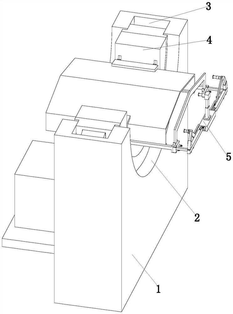
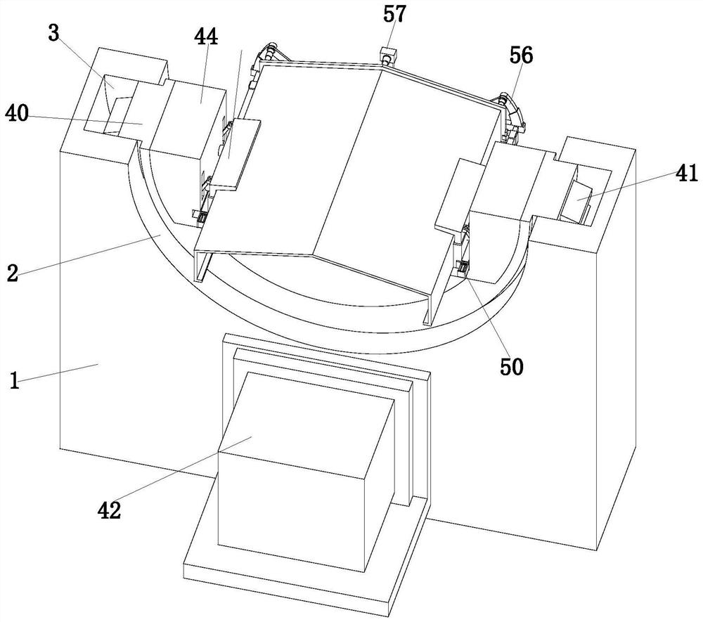
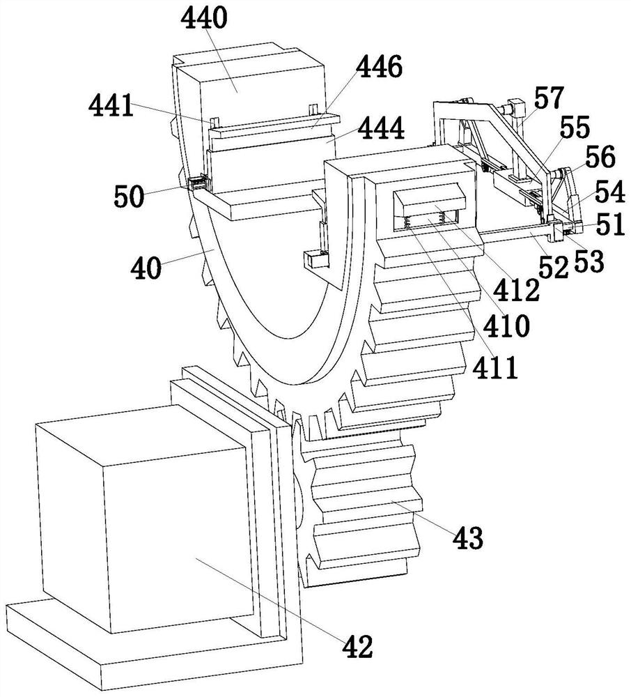
[0032] see figure 1 , an auxiliary tool for welding and forming a machine tool protective cover, comprising a support seat 1; the upper end surface of the support seat 1 is a circular arc surface 2, and the inner wall of the circular arc surface 2 is provided with a ring groove 3, and the ring groove 3 is slidably fitted. A turning unit 4 is installed in a manner, and a docking device 5 is provided on the right side of the support bas...


PUM


Abstract

The invention relates to the technical field of welding tools, in particular to a machine tool protective cover welding forming auxiliary tool. Comprising a supporting seat, the upper end face of the supporting seat is an arc surface, an annular groove is formed in the inner wall of the arc surface, an overturning unit is installed in the annular groove in a sliding fit mode, and a butt joint device is arranged on the right side of the supporting seat and installed on the overturning unit; the problems that in the welding process of a current machine tool protective cover, a limiting plate is in butt joint with the protective cover in a manual lineation mode, the butt joint stability is poor, operation is tedious, and the machining efficiency is low are solved; in the welding process, welding dead corners of the shield need to be turned over manually, and the operation consumes manpower and affects the machining efficiency. The rotating angle of manual rotating of the shield is limited, and the welding quality of the corner is affected. Rapid and accurate butt joint of the shield and the limiting plate is guaranteed, welding operation is facilitated, and the welding quality is improved.

Description

technical field [0001] The invention relates to the technical field of welding tooling, in particular to an auxiliary tooling for welding and forming a protective cover of a machine tool. Background technique [0002] Machine tool shields are used to protect machine tool guide rails, screw rods or drive racks from corrosion and damage from the outside world. Common types of machine tool shields include organ-type shields, steel telescopic shields, etc. [0003] The welding process is commonly used in the processing process of the protective cover of the machine tool. For example, the steel telescopic protective cover is assembled by a plurality of protective covers. Limiting effect between two shields. [0004] However, at present, there are the following problems in the welding process of machine tool shields: First, the shield and the limit plate are often docked with the limit plate and the shield by manual scribing, which is inaccurate and more stable during the docking...

Claims


Application Information

Patent Timeline
Patent Type & Authority Applications(China)
IPC IPC(8): B23K37/04B23K37/047
CPCB23K37/04B23K37/0443B23K37/047Y02P70/10
Inventor 张雪琴
Owner 徐州玖维轩电子科技有限公司
Why Eureka
Try Eureka