A tool adjusting structure and dicing machine

A technology for adjusting structures and dicing machines, which is applied in the field of mechanical transmission and can solve problems such as inability to accurately adjust cutting force

Active Publication Date: 2022-07-15
HEBEI KTHAHCO TECH CO LTD
View PDF9 Cites 0 Cited by
  • Summary
  • Abstract
  • Description
  • Claims
  • Application Information

AI Technical Summary

Problems solved by technology

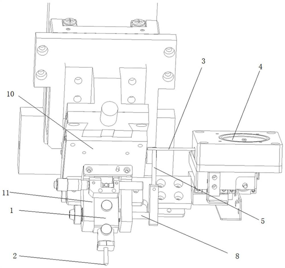
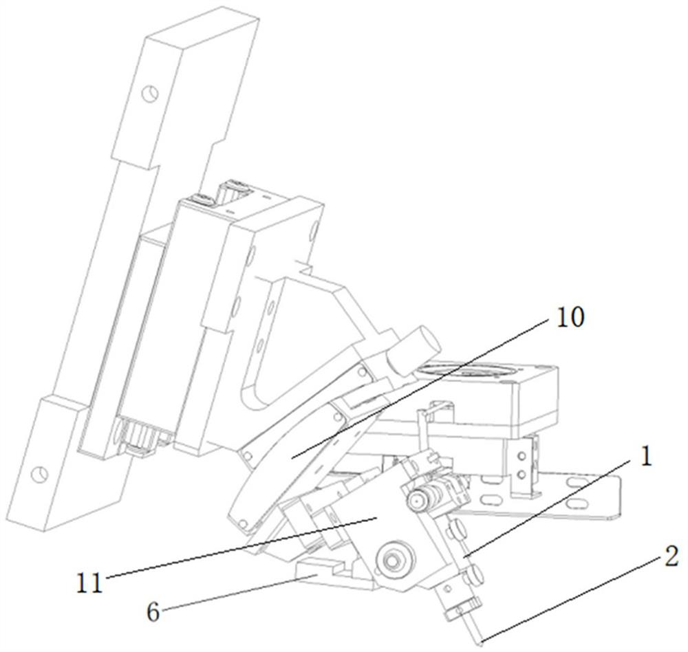
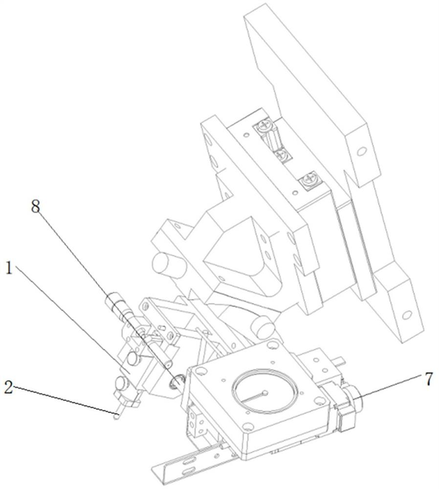
[0004] Therefore, the technical problem to be solved by the present invention is to overcome the defect that the cutting force cannot be precisely adjusted in the prior art, so as to provide a cutter adjustment structure: including

Method used


Image

  • A tool adjusting structure and dicing machine
  • A tool adjusting structure and dicing machine
  • A tool adjusting structure and dicing machine

Examples


Embodiment Construction

[0035] The technical solutions of the present invention will be clearly and completely described below with reference to the accompanying drawings. Obviously, the described embodiments are a part of the embodiments of the present invention, but not all of the embodiments. Based on the embodiments of the present invention, all other embodiments obtained by those of ordinary skill in the art without creative efforts shall fall within the protection scope of the present invention.

[0036] In the description of the present invention, it should be noted that the terms "center", "upper", "lower", "left", "right", "vertical", "horizontal", "inner", "outer", etc. The indicated orientation or positional relationship is based on the orientation or positional relationship shown in the accompanying drawings, which is only for the convenience of describing the present invention and simplifying the description, rather than indicating or implying that the indicated device or element must hav...


PUM


Abstract

The invention provides a cutter adjustment structure and a dicing machine, belonging to the technical field of mechanical transmission. The cutter adjustment structure comprises: a mounting seat, which is fixedly connected with the dicing machine body; a driving member, the driving end is connected with the rotating shaft; the driving member drives the rotating shaft to rotate, changing the abutment force applied when the scriber is in contact with the wafer; the present invention passes the scriber support through the rotating shaft It is installed on the mounting seat, so the scribing knife can rotate around the rotating shaft, and the rotating shaft is driven to rotate by the driving element, and the driving element indirectly drives the scribing knife to rotate around the rotating shaft. On the one hand, the rotation of the scribing knife can change the contact between the scribing knife and the wafer. On the other hand, the force applied by the scribe to the wafer in the direction of the axis of the scribe can be changed, so as to adjust the abutment force applied when the scribe and the wafer are in contact, so as to achieve accurate wafer cutting process. The advantage of adjusting the size of the cutting force.

Description

technical field [0001] The invention relates to the technical field of mechanical transmission, in particular to a tool adjusting structure and a dicing machine. Background technique [0002] It is mainly aimed at optical communication chips made of gallium arsenide and indium phosphide. The wafer needs to be cut before use. The traditional wafer cutting technology is manually cut with a diamond knife. The consumables are large and the strength cannot be determined. The width of the wafer chips is relatively large, uneven, and has poor applicability and low efficiency. [0003] In the prior art, the spring pressure method is used, but the accuracy will be wrong, and the service life of the spring is short, so providing a device that can accurately adjust the cutting force during the wafer cutting process has become the main problem of current wafer cutting. SUMMARY OF THE INVENTION [0004] Therefore, the technical problem to be solved by the present invention is to overc...

Claims


Application Information

Patent Timeline
Patent Type & Authority Patents(China)
IPC IPC(8): B28D5/00B28D7/00
CPCB28D5/0011B28D5/0029B28D5/0058Y02P70/50
Inventor 杨木张文杰张一暾温子勋马修远刘亚洲
Owner HEBEI KTHAHCO TECH CO LTD
Why Eureka
Try Eureka