Venturi air valve
A technology of venturi and air valve, applied in the direction of valve device, valve details, sliding valve, etc., can solve the problems of adjustment, unsatisfactory effect, inability to achieve air volume, etc., and achieve the effect of easy adjustment
- Summary
- Abstract
- Description
- Claims
- Application Information
AI Technical Summary
Problems solved by technology
Method used
Image
Examples
Embodiment 1
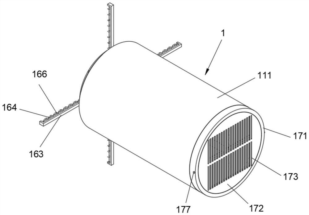
[0043] see Figure 1-Figure 7 As shown, the purpose of this embodiment is to provide a venturi damper, including an air volume valve 1, and the air volume valve 1 at least includes:
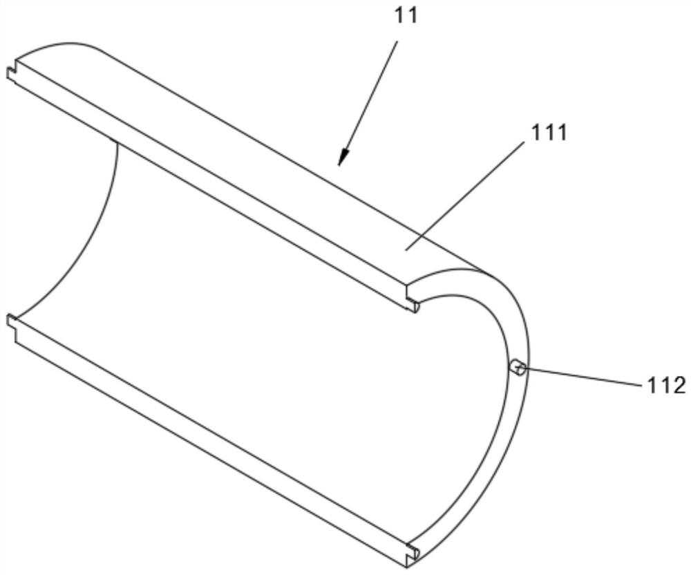
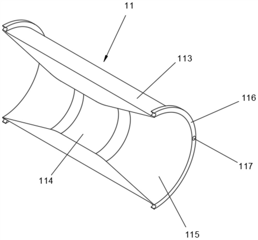
[0044]The pipeline 11, the pipeline 11 includes a casing 111, the casing 111 is a tubular structure, the lateral surfaces of both ends of the casing 111 are symmetrically provided with a plurality of side posts 112, the side posts 112 are cylindrical, and the casing 111 is provided with an inner tube 113, The inner tube 113 is a cylinder, the inner tube 113 is provided with a central port 114 in the middle, and the two ends of the inner tube 113 are provided with ports 115 penetrating the surface thereof. The area is smaller than the cross-sectional area of the port 115, and end rings 116 are provided at both ends of the surface of the inner tube 113. The end rings 116 are annular plates. The side post 112 is plugged and fitted, and the inner tube 113 can be prevented from rotating in the slee...
Embodiment 2
[0052] see Figure 8-Figure 9 As shown, considering that the elastic band 142 cannot completely block the central opening 114, so that the inner tube 113 cannot isolate the passage of air, this embodiment makes the following improvements on the basis of Embodiment 1:
[0053] Among them, in order to ensure the sealing of the inner tube 113, the port 115 at the end of the inner tube 113 away from the servo motor 125 is provided with a side end body 15. The side end body 15 includes a side end frame 151 located in the port 115. The side end frame 151 is a cross structure with a cylindrical protrusion on one side of the middle part. The cylindrical protrusion of the side end frame 151 is provided with a frame groove 152. The frame groove 152 is a circular through hole. The inner surface of 152 is symmetrically provided with a limiting groove 153, the limiting groove 153 is a semi-cylindrical structure groove, and a connecting body 154 is slidably connected in the limiting groove ...
Embodiment 3
[0057] see Figure 10 As shown, since the suction will attract impurities in the air into the inner tube 113, causing the inner tube 113 to be blocked, this embodiment makes the following improvements on the basis of Embodiment 1:
[0058] Among them, in order to prevent debris from entering the inner tube 113, one end of the inner tube 113 is provided with a filter body 17, the filter body 17 includes an outer ring 171, the outer ring 171 is an annular body, and the outer ring 171 is sleeved with one end of the inner tube 113. The outer ring 171 is provided with an outer disk 172, the outer disk 172 is a cylinder, and the outer disk 172 is provided with a through groove 173 running through its surface. The plate 174 is an elongated square plate. By providing the filter body 17 , when the air flows through the through groove 173 , the impurities in the air are intercepted by the grid plate 174 , thereby preventing impurities from entering the inner pipe 113 .
[0059] Further...
PUM
 Abstract
Description
Claims
Application Information
 - R&D Engineer
- R&D Manager
- IP Professional
- Industry Leading Data Capabilities
- Powerful AI technology
- Patent DNA Extraction
Browse by: Latest US Patents, China's latest patents, Technical Efficacy Thesaurus, Application Domain, Technology Topic, Popular Technical Reports.
© 2024 PatSnap. All rights reserved.Legal|Privacy policy|Modern Slavery Act Transparency Statement|Sitemap|About US| Contact US: help@patsnap.com


