
Method for calculating sensitivity of single-ring Rogowski coil current sensor with arbitrary skeleton shape

A technology of current sensors and Rogowski coils, which is applied in the direction of instruments, measuring electrical variables, and measuring devices, can solve the problems of complex 3D model process, long calculation cycle, and poor versatility, and achieve design time saving, convenient calculation, and easy calculation. Effect

Pending Publication Date: 2022-05-27
WUHAN UNIV
View PDF0 Cites 0 Cited by
  • Summary
  • Abstract
  • Description
  • Claims
  • Application Information

AI Technical Summary

Problems solved by technology

[0006] 1. Commonly used finite element calculation software cannot carry out mesh planing calculation for Rogowski coils with densely wound wires (the number of turns is usually several thousand turns, and the diameter of enameled wire is usually less than 0.17mm);
[0007] 2. Based on the finite element simulation software, the real three-dimensional model process of planing the Rogowski coil is relatively complicated and the calculation cycle is long
[0008] 3. The existing theoretical calculation method is only suitable for the ideal specific situation where the measured wire is an infinitely long straight wire that vertically passes through the center of a single-ring circular skeleton Rogowski coil, and is not suitable for current-carrying conductors and single Rogowski coils with arbitrary skeleton shapes, poor versatility

Method used


Image

  • Method for calculating sensitivity of single-ring Rogowski coil current sensor with arbitrary skeleton shape
  • Method for calculating sensitivity of single-ring Rogowski coil current sensor with arbitrary skeleton shape
  • Method for calculating sensitivity of single-ring Rogowski coil current sensor with arbitrary skeleton shape

Examples


Embodiment Construction

[0067] In order to make the objectives, technical solutions and advantages of the present invention clearer, the present invention will be further described in detail below with reference to the accompanying drawings and embodiments. It should be understood that the specific embodiments described herein are only used to explain the present invention, but not to limit the present invention.

[0068] In the embodiment of the present invention, a common Rogowski coil with a circular skeleton and a circular cross-section is selected for description.

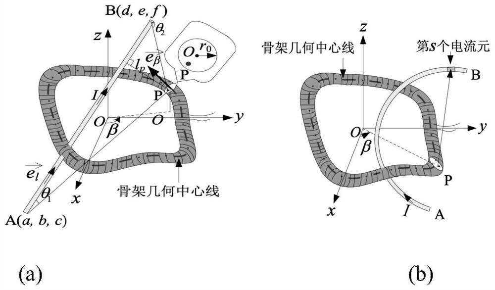
[0069] Step 1, such as figure 1 As shown, a three-dimensional Cartesian coordinate system is established with a point in the Rogowski coil as the coordinate origin. Write down the geometric centerline equation of the Rogowski coil. The geometric centerline also vertically passes through the geometric center of the turn section. The parametric equation of the centerline of the Rogowski coil bobbin is:

[0070]

[0071] In the emb...


PUM


Abstract

The invention discloses a method for calculating the sensitivity of a single-ring Rogowski coil current sensor with any skeleton shape, and the method comprises the steps: building a three-dimensional rectangular coordinate system with a certain point in a Rogowski coil as a coordinate origin, and writing a parameter equation of a geometric center line of the Rogowski coil; when the measured wire is a straight wire, obtaining a unit vector of the current-carrying conductor; calculating the magnetic induction intensity generated by the current-carrying straight conductor at the point P according to the Biot-Savart law; calculating the magnetic flux passing through the section of the wire turn at the beta position; the magnetic flux of each wire turn is added to obtain the magnetic flux of the whole Rogowski coil, and the mutual inductance coefficient of the Rogowski coil and the direct current-carrying conductor is obtained; according to the basic working principle of the Rogowski coil current transformer, the sensitivity of the Rogowski coil can be obtained when wires with any positions and any shapes are measured. The method is high in universality and convenient to calculate, a program is easy to compile for calculation, and the design time is saved; no empirical formula exists in the calculation process, and the calculation precision is high.

Description

technical field [0001] The invention relates to the technical field of AC current measurement, in particular to a method for calculating the sensitivity of a Rogowski coil current sensor with a single-ring arbitrary skeleton shape. Background technique [0002] Current sensors play an important role in electrical safety engineering. Rogowski coil current sensor referred to as Rogowski coil (Rogowski coil) current sensor, also called differential current sensor, named after German physicist Walter Rogowski, has been used for more than 100 years. It is considered to be the best measurement tool for measuring AC current and transient high current. It overcomes many common shortcomings of ordinary sensors that cannot test large or high-frequency currents due to magnetic saturation. The measured current ranges from a few amperes to several thousand amperes. Applications include relay protection, high current, pulse current and transient current, detection and location of serie...

Claims


Application Information

Patent Timeline
IPC IPC(8): G01R35/02
CPCG01R35/02
Inventor 何怡刚刘晓宇
Owner WUHAN UNIV
Learn More