Hot-pressing tank forming mold and forming method for composite material blade of ship propeller

A technology of autoclave molding and composite materials, which is applied in the field of ship propellers, and can solve problems such as the difficulty in ensuring the airtightness of the autoclave molding process, the thick thickness of the corner of the blade root, and the inability to meet the staged molding of large propeller blades, etc. , to achieve the effect of meeting the needs of fractional molding, reducing mold manufacturing costs, and reducing mold costs

Pending Publication Date: 2022-05-31
武汉海威船舶与海洋工程科技有限公司 +3
View PDF1 Cites 3 Cited by
  • Summary
  • Abstract
  • Description
  • Claims
  • Application Information

AI Technical Summary

Problems solved by technology

The mold design has the following deficiencies: (1) The open lateral movable mold block design is difficult to ensure the air tightness required by the autoclave forming process, and is only suitable for the molding process; (2) The mold is only suitable for making blades The blade root is made of prepreg, which is not suitable for the blade whose root is a metal connector; (3) The thickness of the corner of the blade root of a large complex composite blade is very thick, and it is difficult to complete the entire blade at one time. Propeller blade molding, the blade root described in the patent is formed at one time, and combined with the patent CN111873449A, the comparative patent mold is only suitable for small-scale blade molding; (4) This mold cannot meet the needs of step-by-step molding of large propeller blades

Method used


Image

  • Hot-pressing tank forming mold and forming method for composite material blade of ship propeller
  • Hot-pressing tank forming mold and forming method for composite material blade of ship propeller
  • Hot-pressing tank forming mold and forming method for composite material blade of ship propeller

Examples


Embodiment Construction

[0078] In order to have a clearer understanding of the technical features, purposes and effects of the present invention, the specific implementation manners of the present invention will now be described in detail with reference to the accompanying drawings.

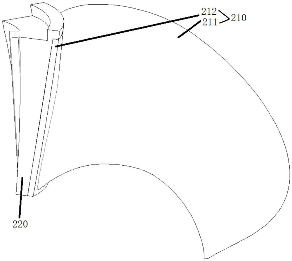
[0079] The present invention proposes an autoclave molding die for a ship propeller composite blade, the autoclave molding die is a single-piece mold, and the composite blade 210 to be manufactured has a structure such as figure 1 As shown, the blade root is a metal connector 220 , and the surface of the metal connector 220 is coated with a composite material outer skin, and the composite material outer skin includes a composite material blade 211 and a composite material blade root 212 .

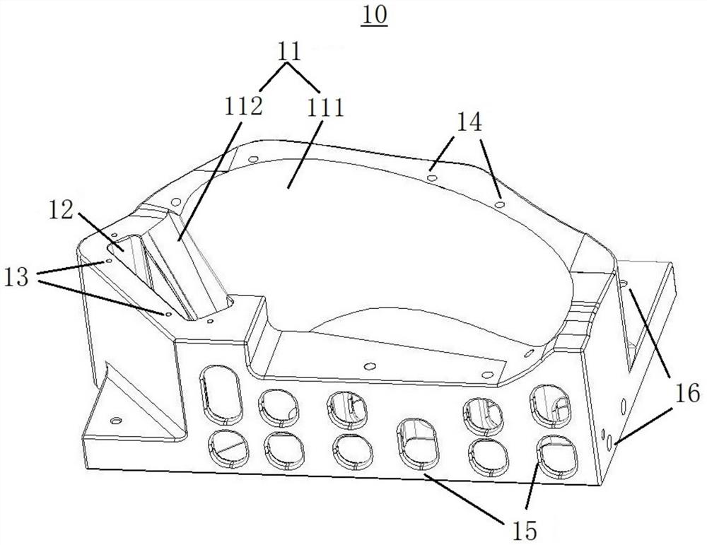
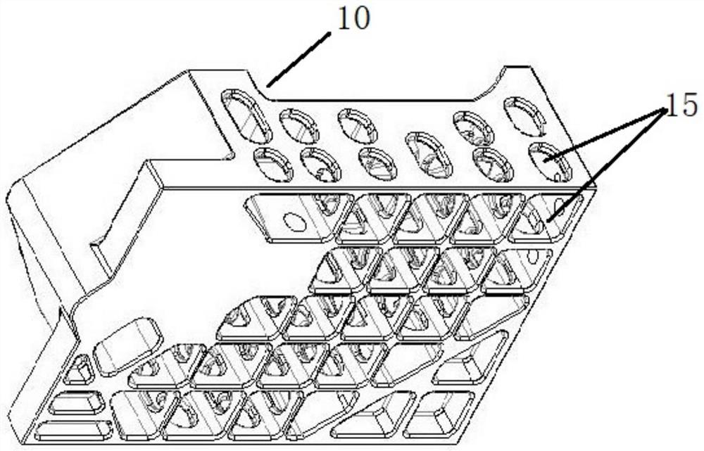
[0080] Such as Figure 2-8 As shown, the autoclave forming mold comprises a main body mold 10, a mold loose block 20, a mold pressing plate 30 and a mold backing plate 40, and the main body mold 10, the mold loose block 20, the mold ...


PUM


Abstract

The invention relates to an autoclave forming die for a composite material blade of a ship propeller. The autoclave forming die comprises a main body die, a die loose piece and a die pressing plate, the main body mold is provided with a paddle cavity matched with a paddle profile value and a loose piece sliding groove matched with the mold loose piece, the paddle cavity comprises a blade cavity and a blade root cavity, the loose piece sliding groove is arranged close to the blade root cavity, and the mold loose piece is inserted into the loose piece sliding groove through an opening in the upper end of the loose piece sliding groove; the die loose piece is provided with a blade root mounting groove matched with the metal connecting piece, and an opening is formed in one side, facing the paddle cavity, of the die loose piece; the mold pressing plate covers an opening in the upper end of the movable block sliding groove, is fixedly connected with the main body mold and is used for applying pre-tightening pressure to enable a product to be closed in place; by additionally arranging the die base plate, the multi-time forming requirement of a large paddle can be met, and other paddles with similar structures can also be formed. The autoclave forming process of the large propeller composite material blade can be achieved, the high yield is guaranteed, meanwhile, the production efficiency can be improved, and the mold cost is reduced.

Description

technical field [0001] The invention relates to the technical field of ship propellers, in particular to an autoclave forming mold and a forming method for composite material blades of ship propellers. Background technique [0002] At present, domestic conventional ship propellers are basically made of metal. As marine systems have higher requirements for propeller propulsion efficiency, noise reduction and weight reduction, composite materials will gradually become an industry trend. [0003] Due to the extremely complex structure and shape of the ship propeller composite material blade, it has high quality and size requirements. For example, the curvature of the blade is very high, the connection requirements of the blade root are high and the form is different, the thickness of the blade root is large, and the blade tip is very thin and easy to deform. Very high requirements are placed on the mold from two perspectives of technology and cost. Under the premise of ensur...

Claims


Application Information

Patent Timeline
Patent Type & Authority Applications(China)
IPC IPC(8): B29C70/34B29C70/68B29C70/54B29L31/08
CPCB29C70/342B29C70/345B29C70/681B29C70/54B29L2031/087
Inventor 张磊赵威成天健张建设刘敏黄坤李开阳朱锡
Owner 武汉海威船舶与海洋工程科技有限公司
Why Eureka
Try Eureka