
Buried garbage can facilitating garbage collection and garbage collection vehicle

A buried type and garbage bin technology, which is applied in garbage collection, garbage cans, garbage containers, etc., can solve the problems of not being applicable to a large municipal area, inconvenient and quick cleaning of garbage, etc., and achieve a small overall operation area and use scenarios The effect of small limitations and fast collection of garbage

Inactive Publication Date: 2022-05-31
苏州苏工重工科技有限公司
View PDF2 Cites 0 Cited by
  • Summary
  • Abstract
  • Description
  • Claims
  • Application Information

AI Technical Summary

Problems solved by technology

[0008] The purpose of the present invention is to provide a buried garbage bin and a garbage collection vehicle that are convenient for collecting garbage, so as to solve the problems in the above-mentioned background technology that it is not suitable for large-scale municipal use, and it is inconvenient to quickly clean up garbage.

Method used


Image

  • Buried garbage can facilitating garbage collection and garbage collection vehicle
  • Buried garbage can facilitating garbage collection and garbage collection vehicle
  • Buried garbage can facilitating garbage collection and garbage collection vehicle

Examples


Embodiment 1

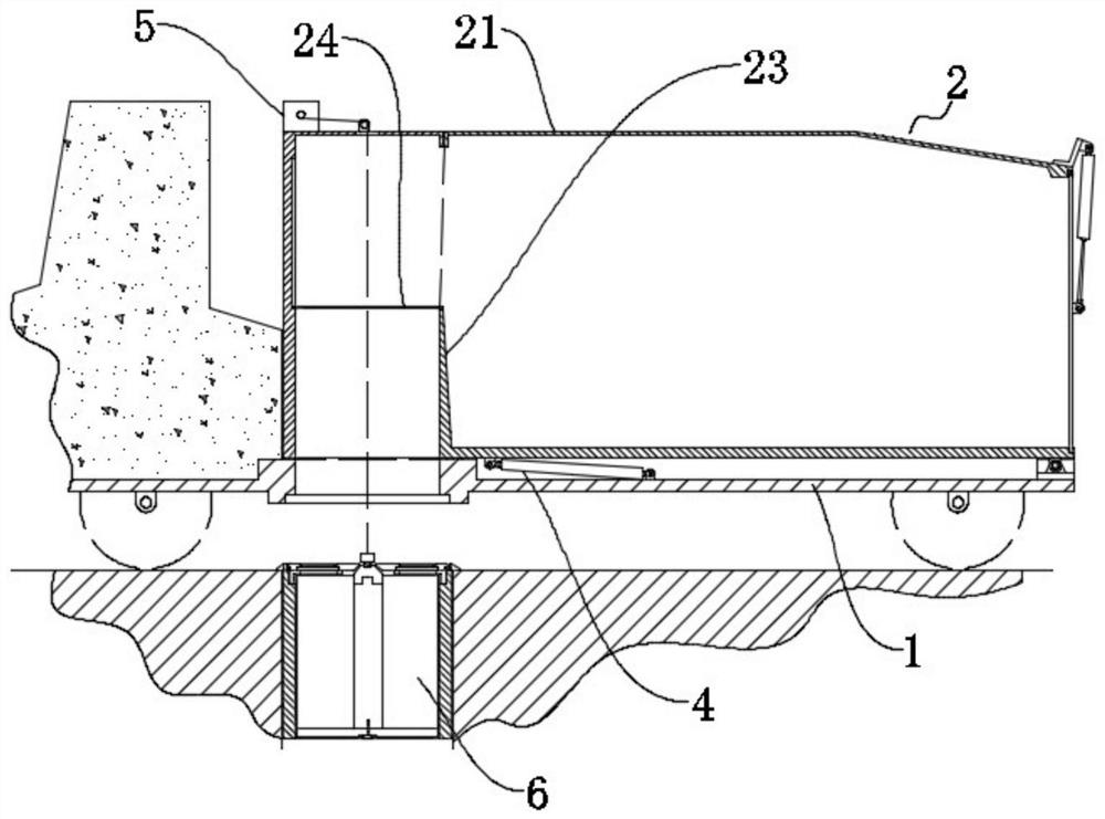
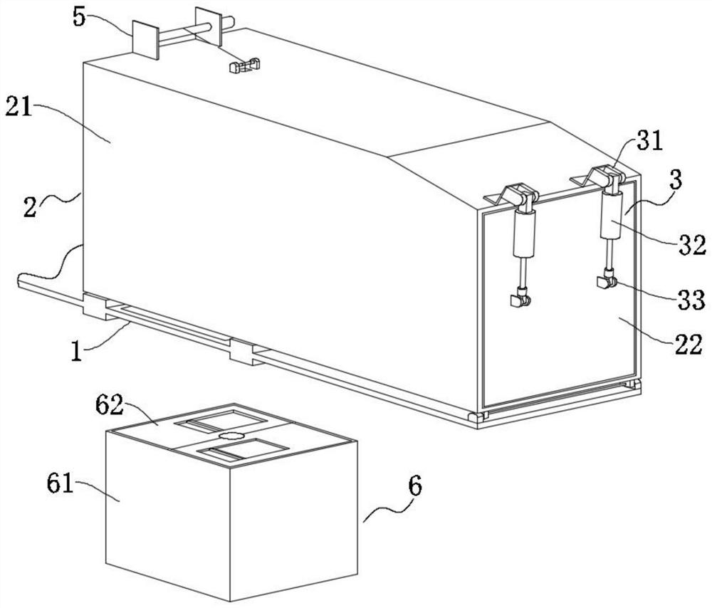
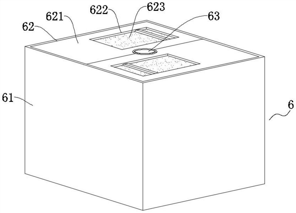
[0034] An underground garbage bin and a garbage collection truck for collecting garbage, comprising a vehicle frame 1 and an underground garbage bin 6, the underground garbage bin 6 is buried on the ground, and the top of the underground garbage bin 6 is exposed to the ground, The bottom of the frame 1 is provided with a through opening, and a garbage hopper 2 is movably assembled on the frame 1. The garbage hopper 2 includes a first box body 21, and a partition plate 23 is fixed inside the first box body 21. The partition plate 23 Divide the first box body 21 into a garbage storage cavity and a garbage throwing cavity, such as figure 1 As shown, the left side of the partition 23 is the garbage throwing cavity, and the right side is the garbage storage cavity.

[0035] The lower surface of the first box body 21 is provided with a garbage inlet, one end of the garbage inlet is opposite to the through opening, the other end of the garbage inlet is communicated with the garbage t...

Embodiment 2

[0049] Embodiment 2, on the basis of Embodiment 1, the difference between Embodiment 2 is that, such as Figure 1-8 As shown in the figure, the side of the first box 21 protrudes outward, the garbage throwing cavity is located in the protruding part, and there is a sloping plate in the garbage throwing cavity of the protruding part to guide the garbage into the garbage storage cavity, and the frame 1 cooperates with the first box. The side of 21 protrudes outward. With this shape design, the vehicle does not need to drive above the buried garbage bin 6, and the buried garbage bin 6 laid on the sidewalk can also easily collect garbage.


PUM


Abstract

The invention relates to the technical field of garbage temporary storage or garbage removal, in particular to a buried garbage can convenient for garbage collection and a garbage collection truck, the buried garbage can convenient for garbage collection comprises a frame and a buried garbage can, the bottom of the frame is provided with a through opening, the frame is movably provided with a garbage hopper, and the garbage hopper comprises a first box body; a partition plate is fixed in the first box body and divides the interior of the first box body into a garbage storage cavity and a garbage throwing cavity, a garbage inlet is formed in the lower surface of the first box body, one end of the garbage inlet is opposite to the through opening, and the other end of the garbage inlet communicates with the garbage throwing cavity; the bottom of one end of the first box body is rotationally connected with the frame through a shaft pin, and a lifting mechanism is assembled on the top of the other end of the first box body. Through mutual cooperation of the garbage collection vehicle and the buried garbage can, quick garbage collection is achieved, laying is facilitated, and the garbage collection vehicle is suitable for large-scale municipal use.

Description

technical field [0001] The invention relates to the technical field of garbage temporary storage or garbage removal, in particular to an underground garbage bin and a garbage collection vehicle which are convenient for collecting garbage. Background technique [0002] Compared with traditional garbage bins, buried garbage bins can reduce the floor area occupied, which is helpful for cleaning personnel to clean up the road and put garbage. However, the cleaning of garbage in underground garbage bins forms batch management, which is more difficult than traditional internal garbage bins. [0003] In this regard, Chinese Patent Publication No.: CN211544733U discloses a lifting system for an underground garbage bin for accommodating a box body, which includes: a closed space, and a lifting frame assembly configured to be located at and fixed to the bottom of the closed space , and a box body can be placed thereon; an upper cover assembly configured to cover the opening at the upp...

Claims


Application Information

Patent Timeline
Patent Type & Authority Applications(China)
IPC IPC(8): B65F3/08B65F3/26B65F1/16B65F1/14
CPCB65F3/08B65F3/26B65F1/1607B65F1/1457B65F2003/006Y02W30/10
Inventor 傅秀清陆飞陶峰孙一伟
Owner 苏州苏工重工科技有限公司
Learn More