Grille steel frame structure with spiral stirrups and construction method thereof

A grid steel frame and spiral technology, which is applied in the grid steel frame structure and its construction field, can solve the problems of poor bearing capacity, insufficient rigidity of the steel frame, and instability of the steel frame, so as to improve the deformation resistance and improve the construction efficiency. Efficiency, improve overall effect

Pending Publication Date: 2022-05-31
CHINA RAILWAY FIRST SURVEY & DESIGN INST GRP +1
View PDF0 Cites 0 Cited by
  • Summary
  • Abstract
  • Description
  • Claims
  • Application Information

AI Technical Summary

Problems solved by technology

When the lithology of the surrounding rock in the tunnel is poor, grid steel frames and section steel frames are generally installed in the primary support to enhance the bearing capacity of the primary support. , reinforced mesh, and shotcrete combine to form a joint support and enhance the effectiveness of the support. The stress condition is better and the void behind the lining can be effectively reduced. However, the grid steel frame has poorer rigidity than the I-beam, and the early bearing capacity Poor, low degree of processing and automatic welding, because the welding part of the traditional grid steel frame is inside the grid, and requires double-sided welding, the construction is inconvenient, and problems such as weld damage to steel bars often occur, and the rigidity of the steel frame is insufficient. The bearing capacity is poor, the steel frame is prone to instability, and it is difficult to ensure the full strength of the initial support

Method used


Image

  • Grille steel frame structure with spiral stirrups and construction method thereof
  • Grille steel frame structure with spiral stirrups and construction method thereof
  • Grille steel frame structure with spiral stirrups and construction method thereof

Examples


Embodiment Construction

[0033] In order to more clearly understand the above objects, features and advantages of the present disclosure, the solutions of the present disclosure will be further described below. It should be noted that, in the case of no conflict, the embodiments of the present disclosure and the features in the embodiments can be combined with each other.

[0034] In the following description, many specific details are set forth in order to fully understand the present disclosure, but the present disclosure can also be implemented in other ways than described here; obviously, the embodiments in the description are only some of the embodiments of the present disclosure, and Not all examples.

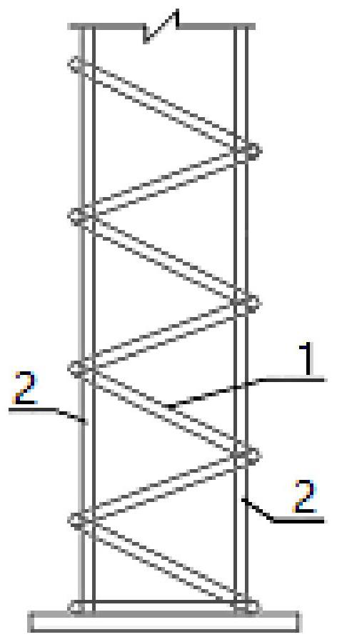
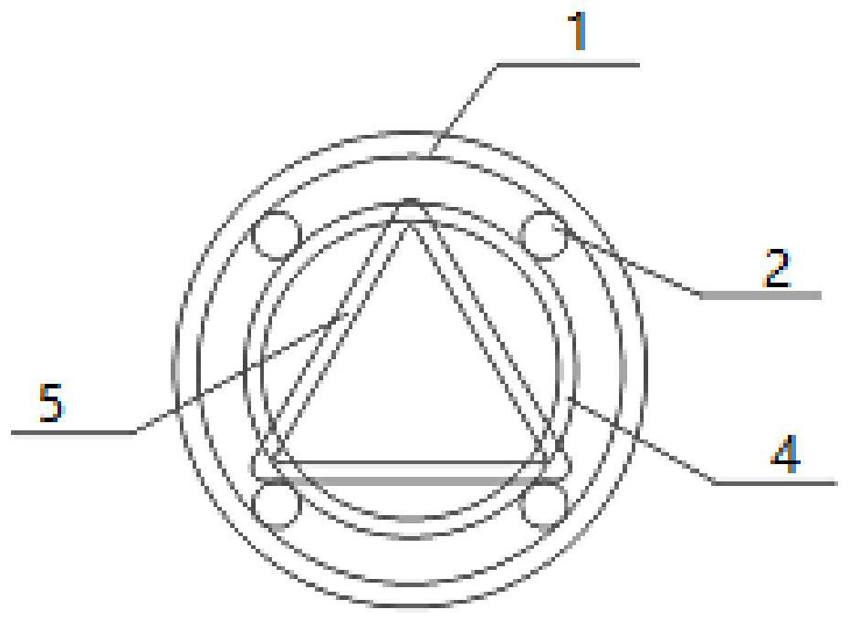
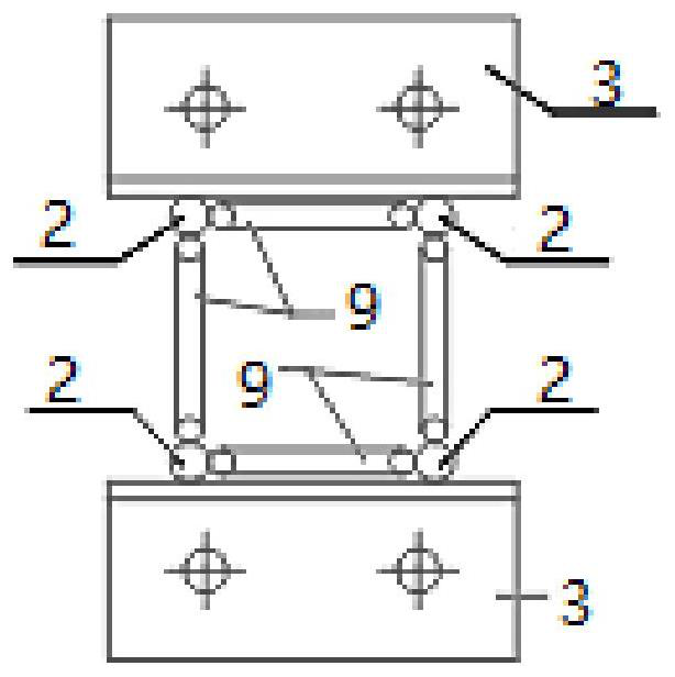
[0035] combine Figure 1 to Figure 3 As shown, some embodiments of the present disclosure provide a grid steel frame structure with spiral stirrups, including a plurality of arch units, the arch units are arched structures, and include a plurality of connected arch segments, Multiple arch units...


PUM


Abstract

The invention provides a grating steel frame structure with spiral stirrups and a construction method of the grating steel frame structure, and relates to the technical field of tunnel and underground engineering, the grating steel frame structure comprises a plurality of arch frame units formed by connecting arch frame sections, and each arch frame section comprises the corresponding stirrup, a main rib, a positioning rib and a connector connecting steel bar; the connecting plates are arranged at the two ends of the arch frame sections and used for being connected with the adjacent arch frame sections, and the connectors are arranged between the adjacent main reinforcements to be connected with the reinforcing steel bars, so that the rigidity of the ends of the arch frame units and the stability of connection between the adjacent arch frame sections are improved; in addition, stirrups of spiral structures are arranged on the peripheries of the main ribs arranged on the peripheries of the positioning ribs, so that the integrality of the arch frame unit is improved, the deformation resistance is improved, materials can be saved, and the construction efficiency is improved. Meanwhile, the wrapping property of sprayed concrete is better, a supporting structure can be formed as soon as possible, and the self-bearing capacity of surrounding rock is exerted.

Description

technical field [0001] The disclosure relates to the technical field of tunnels and underground engineering, in particular to a grid steel frame structure with spiral stirrups and a construction method thereof. Background technique [0002] Most of the current drill-and-blast tunnels use composite lining, including primary support and molded secondary lining. When the lithology of the surrounding rock in the tunnel is poor, grid steel frames and section steel frames are generally installed in the primary support to enhance the bearing capacity of the primary support. , reinforced mesh, and shotcrete combine to form a joint support and enhance the effectiveness of the support. The stress condition is better and the void behind the lining can be effectively reduced. However, the grid steel frame has poorer rigidity than the I-beam, and the early bearing capacity Poor, low degree of processing and automatic welding, because the welding part of the traditional grid steel frame ...

Claims


Application Information

Patent Timeline
Patent Type & Authority Applications(China)
IPC IPC(8): E21D11/18
CPCE21D11/18
Inventor 李国良李雷黄双林李宁刘建红刘国庆司剑钧杨木高王煦霖丁彦杰
Owner CHINA RAILWAY FIRST SURVEY & DESIGN INST GRP
Why Eureka
Try Eureka