
Energy-saving cutting device for continuous casting billet cutting

A cutting device and energy-saving technology, which is applied in the field of energy-saving cutting devices for continuous casting slab cutting, can solve problems such as increased labor intensity, easy splashing around, and potential safety hazards, and achieves reduced labor intensity, reduced splash range, and convenient The effect of rotation

Active Publication Date: 2022-06-03
LIANFENG STEEL (ZHANGJIAGANG) CO LTD
View PDF8 Cites 0 Cited by
  • Summary
  • Abstract
  • Description
  • Claims
  • Application Information

AI Technical Summary

Problems solved by technology

Aiming at the above-mentioned shortcomings in the prior art, the present invention provides an energy-saving cutting device for continuous casting slab cutting, which can effectively solve the problem in the prior art that the temperature of the continuous casting slab itself is relatively high, and it does not need too much heat to cut The metal can be heated to the ignition point. During the cutting process, the molten metal is blown by the fast-flowing gas, and it is easy to splash around, which is easy to accidentally injure people and pose a safety hazard. At the same time, a large amount of metal impurities produced after flame cutting need to be cleaned manually. The problem of increasing labor intensity

Method used


Image

  • Energy-saving cutting device for continuous casting billet cutting
  • Energy-saving cutting device for continuous casting billet cutting
  • Energy-saving cutting device for continuous casting billet cutting

Examples


Embodiment

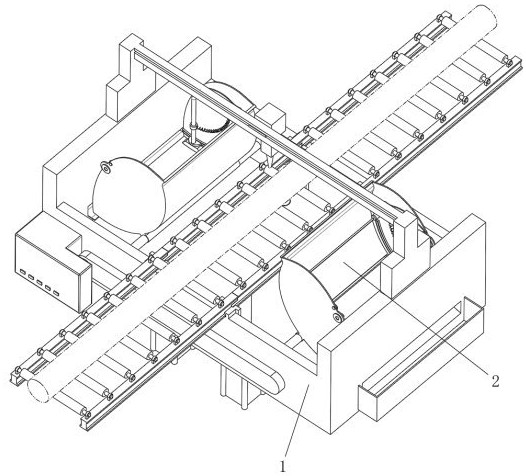
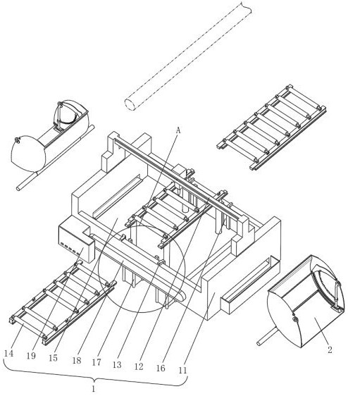
see Figure 1-Figure 8 , the present invention provides a technical solution: an energy-saving cutting device for continuous casting billet cutting, comprising:

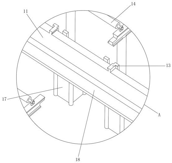
The operating body 1, the operating body 1 includes a placing seat 11, the top of the placing seat 11 is provided with a cutting device 12, and the placing seat 11 is fitted with a conveying frame 14 through a limit block 13 arranged on the top of the placing seat 11;

Placement 2. Placement 2 includes recovery boxes 21. There are two recovery boxes 21 and are symmetrically distributed with the conveying frame 14 as the center. The box 21 is slidably installed with a scraper member 24 through a track 23 provided on the inner wall thereof, and the outer side of the scraper member 24 is adapted to the inner wall of the recovery box 21 .

[0027] There is a working cavity 15 inside the placing seat 11. The conveying frame 14 includes an electric guide rail and rollers. The electric guide rail adopts a segmented design, an...


PUM


Abstract

The invention discloses a continuous casting billet cutting energy-saving type cutting device which comprises an operation main body, the operation main body comprises a placing seat, a cutting device is arranged at the top of the placing seat, the placing seat is provided with a conveying frame and a placing piece in a clamped mode through a limiting block arranged at the top of the placing seat, and the placing piece comprises a recycling box. The number of the recycling boxes is two, and the recycling boxes are symmetrically distributed with the conveying frame as the center. The energy-saving cutting device for cutting the continuous casting billet can effectively solve the problems that in the prior art, the temperature of the continuous casting billet is high, metal can be heated to the ignition point without excessive heat, in the cutting process, molten metal is blown by fast flowing gas and is prone to splashing to the periphery, people are prone to be accidentally injured, potential safety hazards exist, and the cutting efficiency is high. And meanwhile, a large amount of metal impurities generated after flame cutting need to be manually cleaned, and the labor intensity is increased.

Description

technical field [0001] The invention relates to the technical field of heating cutting, in particular to an energy-saving cutting device for cutting a continuous casting billet. Background technique [0002] Continuous casting and cutting is a method of using molten steel to solidify and form in the process of producing various steel products in steel plants. The specific method is that the molten steel continuously passes through the water-cooled crystallizer, solidifies into a hard shell, and then continuously pulls out from the outlet at the bottom of the crystallizer. [0003] The flame cutting of metal is a process of combustion reaction between metal and oxygen. The function of gas is to release heat through its own combustion to heat the metal to the ignition point. Due to the high temperature of the continuous casting billet itself, the metal can be removed without excessive heat. It is heated to the ignition point to cut off the billet; however, during the cutting ...

Claims


Application Information

Patent Timeline
Patent Type & Authority Applications(China)
IPC IPC(8): B22D11/126B22D11/128
CPCB22D11/126B22D11/1284Y02P70/10
Inventor 石磊张小伟祁成
Owner LIANFENG STEEL (ZHANGJIAGANG) CO LTD
Learn More