Laser lens polishing device

A technology of laser lens and grinding mechanism, applied in grinding/polishing safety device, optical surface grinder, lens, etc., can solve the problem of not pointing out and so on

Active Publication Date: 2022-06-03
HARBIN UNIV
View PDF10 Cites 2 Cited by
  • Summary
  • Abstract
  • Description
  • Claims
  • Application Information

AI Technical Summary

Problems solved by technology

[0002] Optical lenses are of irreplaceable importance in the field of optics. At present, only a few countries in the world have relatively complete optical lens grinding technology. There is no technology in the prior art that can adjust the degree of grinding arc according to different usage req

Method used


Image

  • Laser lens polishing device
  • Laser lens polishing device
  • Laser lens polishing device

Examples


Embodiment Construction

[0026] The present invention will be further described in detail below in conjunction with the accompanying drawings.

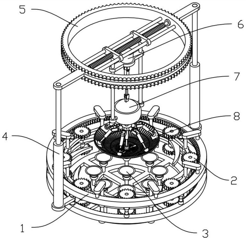
[0027] like Figures 1 to 10 As shown, in order to solve the technical problem of how to adjust the radian of lens grinding according to different usage requirements, the structure and function of a laser lens grinding device are described in detail below;

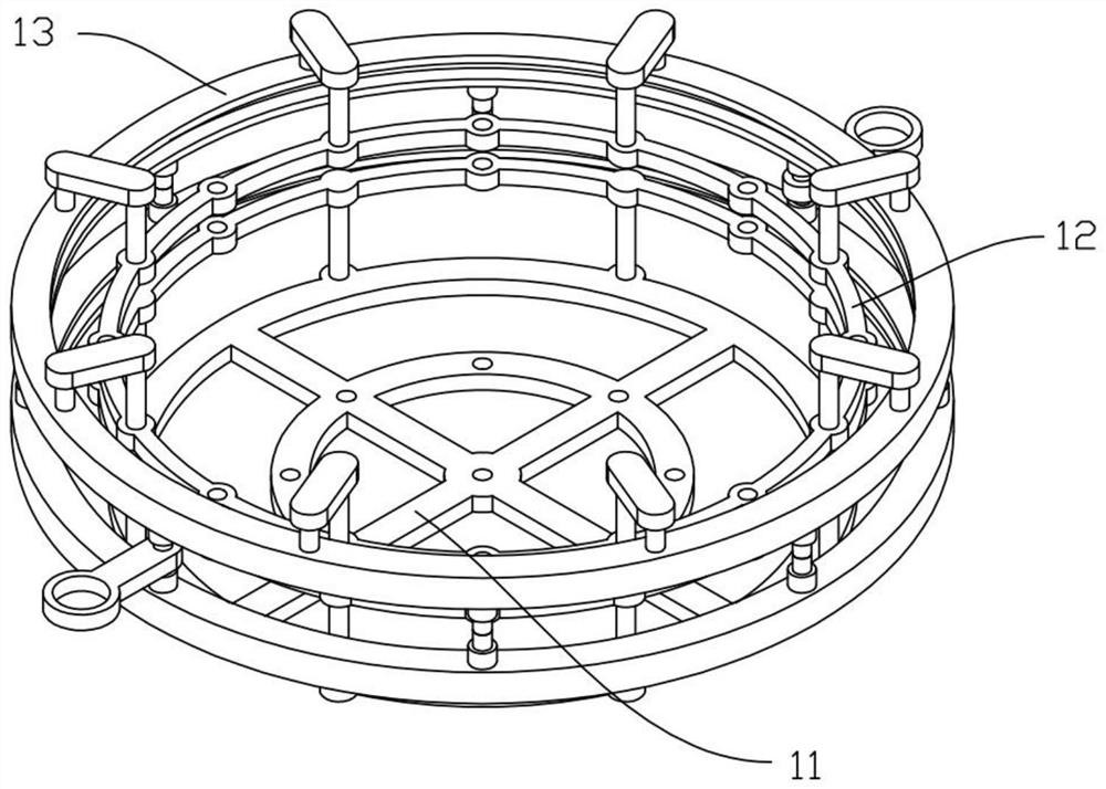
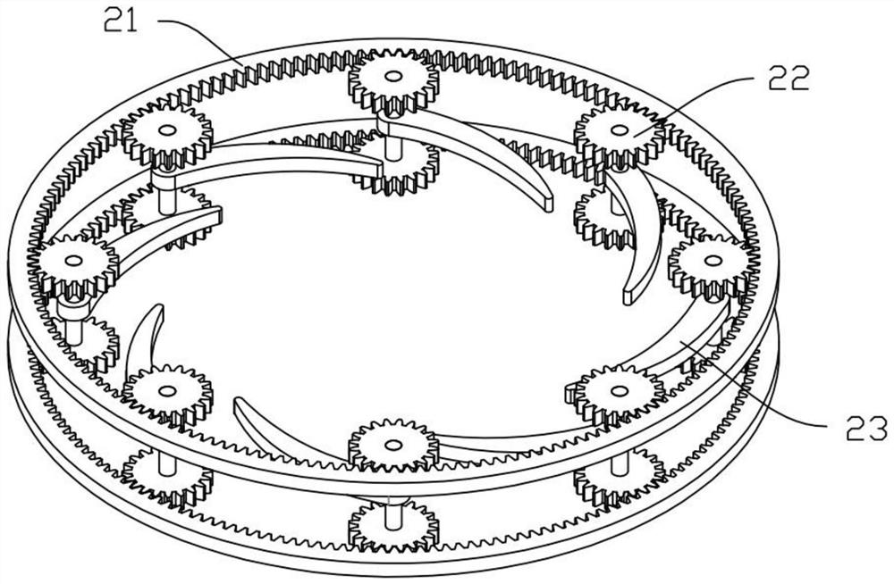
[0028] A laser lens grinding device, comprising a processing bracket 1, a clamping mechanism 2, a supporting mechanism 3, a lifting mechanism 4, a rotating mechanism 5, a swing mechanism 6, an expansion mechanism 7 and a grinding mechanism 8;

[0029] During use, the expansion mechanism 7 drives the polishing mechanism 8 to expand and deform, and then adjusts the bending angle of the polishing mechanism 8. The rotating mechanism 5 drives the swing mechanism 6 to rotate, the swing mechanism 6 drives the expansion mechanism 7 to rotate, and the expansion mechanism 7 drives the polishing mechanism. 8 is rot...


PUM


Abstract

The invention relates to lens polishing, in particular to a laser lens polishing device which comprises a machining support, a clamping mechanism, a supporting mechanism, a lifting mechanism, a rotating mechanism, a swing mechanism, an expansion mechanism and a polishing mechanism. The machining support comprises a bottom support, a supporting ring and a gear ring frame, and the clamping mechanism comprises a gear ring, a gear and a clamping arc plate; the supporting mechanism comprises a telescopic mechanism I, an arc cavity I, a ball I and a suction cup I, the lifting mechanism comprises a telescopic mechanism I and a lifting support, the rotating mechanism comprises a rotating ring, a sliding column and a threaded rod, and the swinging mechanism comprises a swinging support, a rotating motor, a swinging connecting rod, a sliding connecting rod and an arc cavity II. The expansion mechanism comprises a ball II, a telescopic mechanism III, a telescopic mechanism IV, a ball III, a telescopic mechanism V and a ball IV, the grinding mechanism comprises a grinding frame, an arc cavity III and an arc cavity IV, and the grinding radian of the lens can be adjusted according to different use requirements.

Description

technical field [0001] The present invention relates to lens polishing, and more specifically relates to a laser lens polishing device. Background technique [0002] Optical lenses are of irreplaceable importance in the field of optics. At present, only a few countries in the world have relatively complete optical lens grinding technology. There is no technology in the existing technology to adjust the degree of grinding arc according to different use requirements, such as The patent number CN214771042U is named an ultra-thin glass-plastic 4K lens grinding device. Although the patent proposes a technical solution for clamping and grinding the lens, the patent does not indicate how to adjust the grinding arc according to different usage requirements. SUMMARY OF THE INVENTION [0003] The purpose of the present invention is to provide a laser lens grinding device, which can adjust the radian of lens grinding according to different usage requirements. [0004] The object of ...

Claims


Application Information

Patent Timeline
IPC IPC(8): B24B13/00B24B13/005B24B41/02B24B55/00
CPCB24B13/00B24B13/0055B24B41/02B24B55/00
Inventor 刘群张玉军
Owner HARBIN UNIV
Why Eureka
Try Eureka