High-stability superconductor electromagnetic wire pay-off device

A high-stability, pay-off device technology, which is applied in the usage, transportation and packaging of superconductor elements, thin material processing, etc., can solve the problems that the electromagnetic wire cannot recover naturally and the plastic deformation of the metal wire, etc., so as to improve convenience and improve The effect of stability

Pending Publication Date: 2022-06-03
安徽聚虹电器有限公司
View PDF7 Cites 0 Cited by
  • Summary
  • Abstract
  • Description
  • Claims
  • Application Information

AI Technical Summary

Problems solved by technology

[0004] In order to overcome the deficiencies of the prior art, the present invention provides a high-stability superconductor electromagnetic wire pay-off device. Through the adjustment plates and adjustment structures provided, the four sets of adjustment plates can be expanded outwards through the adjustment structures, and the outside of the adjustment plates The diameter is enlarged, so that the electromagnetic wires of different diameters will not be bent excessively when they are wound on the surface of the adjusting plate, and it is avoided that the diameter of the rotating roller cannot be changed. When winding on the wheel, the bending range is relatively large, which may easily lead to plastic deformation of the metal wire inside the magnet wire, resulting in the fact that the released magnet wire cannot naturally return to a straight state, requiring additional straightening processing, which improves the safety of the device. Convenience

Method used


Image

  • High-stability superconductor electromagnetic wire pay-off device
  • High-stability superconductor electromagnetic wire pay-off device
  • High-stability superconductor electromagnetic wire pay-off device

Examples


Embodiment

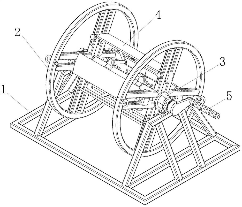
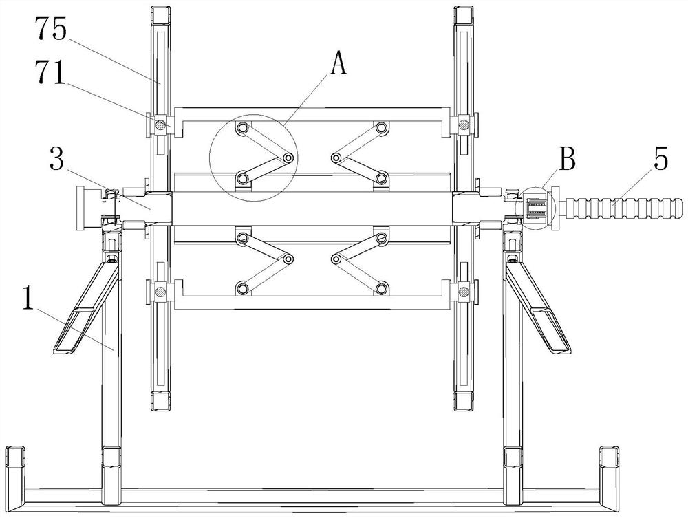
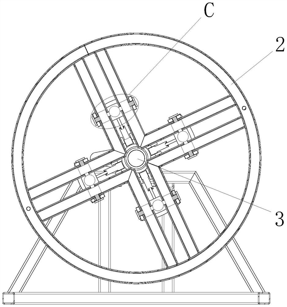
[0031] see figure 1 - Figure 7 , a high-stability superconductor electromagnetic wire pay-off device, comprising a frame 1, a rotating ring 2, a shaft 3, an adjustment plate 4 and a turning handle 5, the frame 1 is rotatably connected with a shaft 3, and the shaft 3 is sleeved on both sides There is a rotating ring 2, the right side of the shaft rod 3 is provided with a turning handle 5, and the surface of the shaft rod 3 is provided with four groups of adjustment plates 4 through two sets of adjustment structures 6, and the adjustment structure 6 includes two sets of sets on the surface of the shaft rod 3. The collar 61 , the four groups of first hinges 62 arranged on the outer wall surface of the collar 61 , the first rotating shaft 63 arranged inside the first hinge 62 , and the first connecting rod whose one end is sleeved on the surface of the first rotating shaft 63 64. A second rotating shaft 65 arranged at the other end of the first connecting rod 64, a second connec...


PUM


Abstract

The invention discloses a high-stability superconductor electromagnetic wire pay-off device which comprises a frame, a rotating ring, a shaft rod, four sets of adjusting plates and a rotating handle, and the surface of the shaft rod is provided with the four sets of adjusting plates through two sets of adjusting structures. The adjusting structure comprises two sets of lantern rings arranged on the surface of the shaft rod in a sleeving mode, four sets of first hinge pieces arranged on the surfaces of the outer walls of the lantern rings, a third rotating shaft penetrating through the other end of the second connecting rod and second hinge pieces arranged at the two ends of the third rotating shaft. By arranging an adjusting plate, an adjusting structure and the like, the problems that the diameter of a rotating roller cannot be changed, when an electromagnetic wire with the large diameter is wound, the bending amplitude of the electromagnetic wire is large when the electromagnetic wire is wound on the rotating roller, plastic deformation of a metal wire in the electromagnetic wire is likely to happen, and the electromagnetic wire is damaged are effectively solved. And the problem that the released electromagnetic wire cannot be naturally recovered to a linear state, and additional straightening processing operation needs to be carried out is solved, and the convenience of the device is improved.

Description

technical field [0001] The invention relates to the technical field of superconductor electromagnetic wires, in particular to a pay-off device for superconductor electromagnetic wires with high stability. Background technique [0002] Magnet wire, also known as winding wire, is an insulated wire used to manufacture coils or windings in electrical products. Magnet wire is usually divided into enameled wire, wrapped wire, enameled wrapped wire and inorganic insulated wire. The production process of magnet wire In the process, it is necessary to go through pay-off, annealing, painting, baking, cooling, and take-up first. During the pay-off process, the coiled metal wire needs to be disassembled and then processed by machinery or manually. In order to ensure the smooth transmission of the metal wire In the next process, a high-stability superconductor electromagnetic wire pay-off device is generally used for auxiliary operations. The existing high-stability superconductor electr...

Claims


Application Information

Patent Timeline
Patent Type & Authority Applications(China)
IPC IPC(8): B65H49/30B65H49/32B65H75/24
CPCB65H49/30B65H49/32B65H75/24B65H2701/36B65H2701/535B65H2701/53Y02E40/60
Inventor 闵加云李阳毛新山蔡春桥李艳川
Owner 安徽聚虹电器有限公司
Why Eureka
Try Eureka