An antifreeze pressure regulating system for aircraft testing and its regulating method
A technology for pressure regulation and aircraft testing, applied in aircraft component testing, control/regulation systems, machine/structural component testing, etc. Indoor wall structure damage and other problems, to ensure the effect of sensitivity
- Summary
- Abstract
- Description
- Claims
- Application Information
AI Technical Summary
Problems solved by technology
Method used
Image
Examples
Embodiment 1
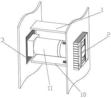
[0056] like figure 2 As shown in the figure, an antifreeze pressure regulation system for aircraft testing includes a thermal insulation regulation channel 1 arranged between the laboratory outer wall panel and the inner thermal insulation storage board, and a thermal insulation regulation channel 1 arranged at the connection between the thermal insulation regulation channel 1 and the internal thermal insulation storage board. An anti-freezing pressure regulating device 2, and an anti-freezing shutter device 3 arranged at the connection between the thermal insulation regulating channel 1 and the outer wall panel of the laboratory;
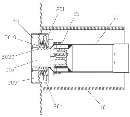
[0057] like figure 2 As shown, the heat preservation adjustment channel 1 includes a first heat preservation channel 10 connected to the laboratory outer wall panel at one end and the inner heat preservation library plate at the other end, and a second heat preservation channel 11 arranged inside the first heat preservation channel 10; The centr...
Embodiment 2
[0077] The difference from Example 1 is:
[0078] like Figure 8 As shown, the support and limit frame 202 is provided with a duct blocking mechanism 22 connected with the air outlet regulating duct 210;
[0079] The duct blocking mechanism 22 includes sliding guide rails 220 fixed on the support limiter 202 and located above and below the air outlet regulating duct 210 . The sealing plate 221 , the fixing members 222 arranged on both sides of the sliding guide 220 , and the telescopic assembly 223 , one end of which is arranged on the sealing plate 221 and the other end is arranged on the fixing member 222 .
Embodiment 3
[0081] The difference from Example 2 is:
[0082] like Figure 9 As shown, the antifreeze shutter device 3 includes a first rectangular frame 30 arranged on the outer wall panel of the laboratory, and a second rectangular frame 31 arranged in the center of the first rectangular frame 30 for connecting the first rectangular frame The frame 30 and the frame fixing member 32 of the second rectangular frame 31, the first shutter assembly 33 disposed between the first rectangular frame 30 and the second rectangular frame 31 and communicating with the first heat preservation channel 10, and the A second shutter assembly 34 inside the second rectangular frame 31 and communicating with the second heat preservation channel 11 .
[0083]The lower end of the blade of the first shutter assembly 33 is close to the outside of the laboratory outer wall panel; the lower end of the blade of the second shutter assembly 34 is close to the inner side of the laboratory outer wall panel.
[0084]...
PUM
 Abstract
Description
Claims
Application Information
 - R&D Engineer
- R&D Manager
- IP Professional
- Industry Leading Data Capabilities
- Powerful AI technology
- Patent DNA Extraction
Browse by: Latest US Patents, China's latest patents, Technical Efficacy Thesaurus, Application Domain, Technology Topic, Popular Technical Reports.
© 2024 PatSnap. All rights reserved.Legal|Privacy policy|Modern Slavery Act Transparency Statement|Sitemap|About US| Contact US: help@patsnap.com


