Laser radar calibration experiment table

A lidar and test bench technology, applied in radio wave measurement systems, instruments, etc., can solve the problems of inconvenient disassembly and assembly, long time, affecting the efficiency of radar calibration, and achieve the effect of strong installation stability and high disassembly and assembly efficiency.

Active Publication Date: 2022-06-03
NANJING UNIV OF TECH +1
View PDF5 Cites 0 Cited by
  • Summary
  • Abstract
  • Description
  • Claims
  • Application Information

AI Technical Summary

Problems solved by technology

[0002] Lidar detects the environment within the laser range and the position and shape of the object by emitting laser light to the target object and receiving the reflected light of the object. Due to errors in the design, processing, assembly and other links of the mechanical part of the laser radar equipment, resulting in There is a certain error in the laser radar itself. At this time, it is necessary to calibrate the laser radar. The laser radar calibration test bench in the prior art generally uses screws to fix the laser calibration plate. This installation method takes a long time. time, and it is inconvenient to disassemble and assemble, which affects the efficiency of radar calibration

Method used


Image

  • Laser radar calibration experiment table
  • Laser radar calibration experiment table
  • Laser radar calibration experiment table

Examples


Embodiment 1

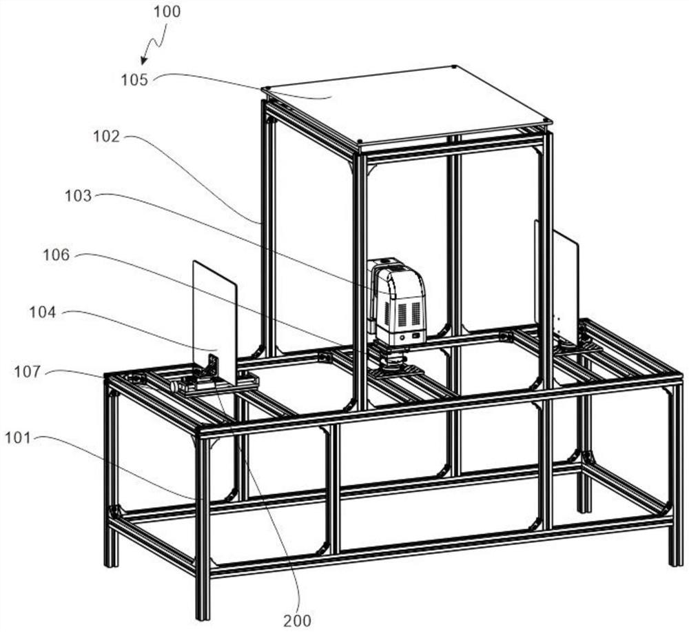
[0029] refer to figure 1 and Figure 4 , which is the first embodiment of the present invention. This embodiment provides a lidar calibration test bench. The lidar calibration test bench includes an experimental assembly 100 and an installation assembly 200. The laser radar is calibrated through the experimental assembly 100. The mounting assembly 200 makes the installation of the laser calibration plate more convenient and stable.

[0030] Specifically, the experimental assembly 100 includes a workbench 101, a support frame 102, a lidar body 103, a first laser calibration plate 104, a second laser calibration plate 105, a mounting seat 106 and an adjustment member 107, and the support frame 102 is fixed on the workbench At the top of 101 , the mounting seat 106 is arranged on the worktable 101 and is located inside the support frame 102 , the lidar body 103 is mounted on the top of the mounting seat 106 , the adjusting members 107 are arranged on both sides of the top of the...

Embodiment 2

[0035] refer to Figures 1 to 3 , is the second embodiment of the present invention, which is based on the previous embodiment.

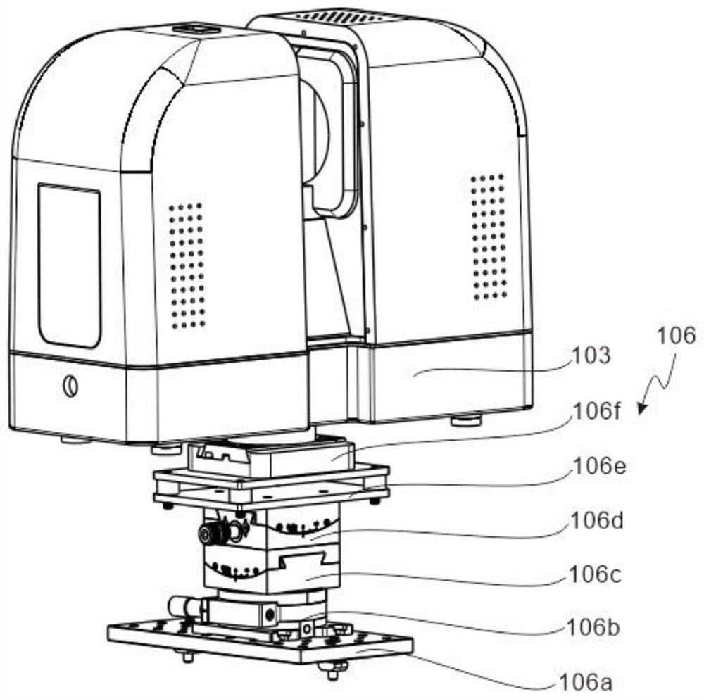
[0036]Specifically, the mounting base 106 includes a first optical breadboard 106a, a rotary displacement stage 106b, an X-axis angular displacement stage 106c, a Y-axis angular displacement stage 106d, a support plate 106e and a quick release fixing base 106f, and the first optical breadboard 106a is provided with On both sides of the top of the worktable 101, the rotation stage 106b is fixed on the top of the first optical breadboard 106a, the X-axis angular stage 106c is fixed with the top of the rotation stage 106b, and the Y-axis angular stage 106d is installed on the X-axis angular stage 106c On the top, the support plate 106e is fixed to the top of the Y-axis angle displacement stage 106d, the quick release fixing seat 106f is fixed on the top of the support plate 106e, and the lidar body 103 is installed on the top of the quick release fixin...

Embodiment 3

[0041] refer to Figures 4 to 7 , is the third embodiment of the present invention, which is based on the first two embodiments.

[0042] Specifically, the receiving member 202 includes a fixed pipe 202a, a connecting pipe 202b, a receiving rod 202c, a receiving plate 202d, and a sealing ball 202e. The fixed pipe 202a is fixed on both sides of the inner side of the connecting frame 201, and the connecting pipe 202b is fixed to the top of the fixed pipe 202a. The receiving rod 202c slides in the connecting pipe 202b, the receiving plate 202d is fixed on the top of the two receiving rods 202c, and the sealing ball 202e slides in the fixing pipe 202a.

[0043] There is a sealing ring inside the fixing tube 202a, and the sealing ball 202e is closely attached to the sealing ring to avoid air leakage in the connecting tube 202b during installation, which affects the clamping effect of the calibration plate. The bottom is in contact with the placement groove to prevent it from being...


PUM


Abstract

A laser radar calibration experiment table disclosed by the present invention comprises a workbench, a support frame, a laser radar body, a first laser calibration plate, a second laser calibration plate, a mounting seat and an adjusting member, the support frame is fixed at the top of the workbench, the mounting seat is arranged on the workbench and is located at the inner side of the support frame, and the adjusting member is fixed on the support frame. The laser radar body is mounted at the top of the mounting base, the adjusting pieces are arranged on the two sides of the top of the workbench, the first laser calibration plate is arranged on the adjusting pieces, and the second laser calibration plate is fixed to the top of the supporting frame; and a mounting assembly. The laser radar is fixed on the experiment assembly for a calibration experiment, then the laser calibration plate is installed through the installation assembly, screws and the like are not needed for fixation, the disassembly and assembly efficiency is higher, and the installation stability is high.

Description

technical field [0001] The invention relates to the technical field of laser radar calibration, in particular to a laser radar calibration test bench. Background technique [0002] By emitting laser light to the target object and receiving the reflected light of the object, the lidar detects the environment within the laser range and the position, shape and other characteristics of the object. Due to the possible errors in the design, processing, and assembly of the mechanical part of the lidar equipment, resulting in There is a certain error in the laser radar itself. At this time, the laser radar needs to be calibrated. The laser radar calibration test bench in the existing technology generally fixes the laser calibration plate by means of screws, etc. This installation method requires a long time. It takes time, and it is inconvenient to disassemble and assemble, which affects the efficiency of radar calibration. SUMMARY OF THE INVENTION [0003] The purpose of this se...

Claims


Application Information

Patent Timeline
Patent Type & Authority Applications(China)
IPC IPC(8): G01S7/497
CPCG01S7/497Y02A90/10
Inventor 张广明尤兵邵敏丁松吕筱东
Owner NANJING UNIV OF TECH
Why Eureka
Try Eureka