Adaptive supply voltage clamping circuit

An adaptive power supply and voltage clamping technology, which is applied in the direction of adjusting electrical variables, instruments, control/regulation systems, etc., can solve problems such as inapplicability, achieve the effect of enhancing self-adaptive ability and improving the scope of application

Pending Publication Date: 2022-06-03
SG MICRO
View PDF0 Cites 0 Cited by
  • Summary
  • Abstract
  • Description
  • Claims
  • Application Information

AI Technical Summary

Problems solved by technology

[0004] The existing clamping circuit only clamps the clamped voltage, that is, the target voltage V1, at a fixed voltage point, and the voltage limit value of the target voltage will not

Method used


Image

  • Adaptive supply voltage clamping circuit
  • Adaptive supply voltage clamping circuit
  • Adaptive supply voltage clamping circuit

Examples


Embodiment 1

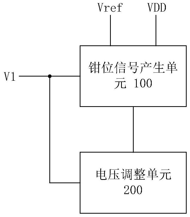
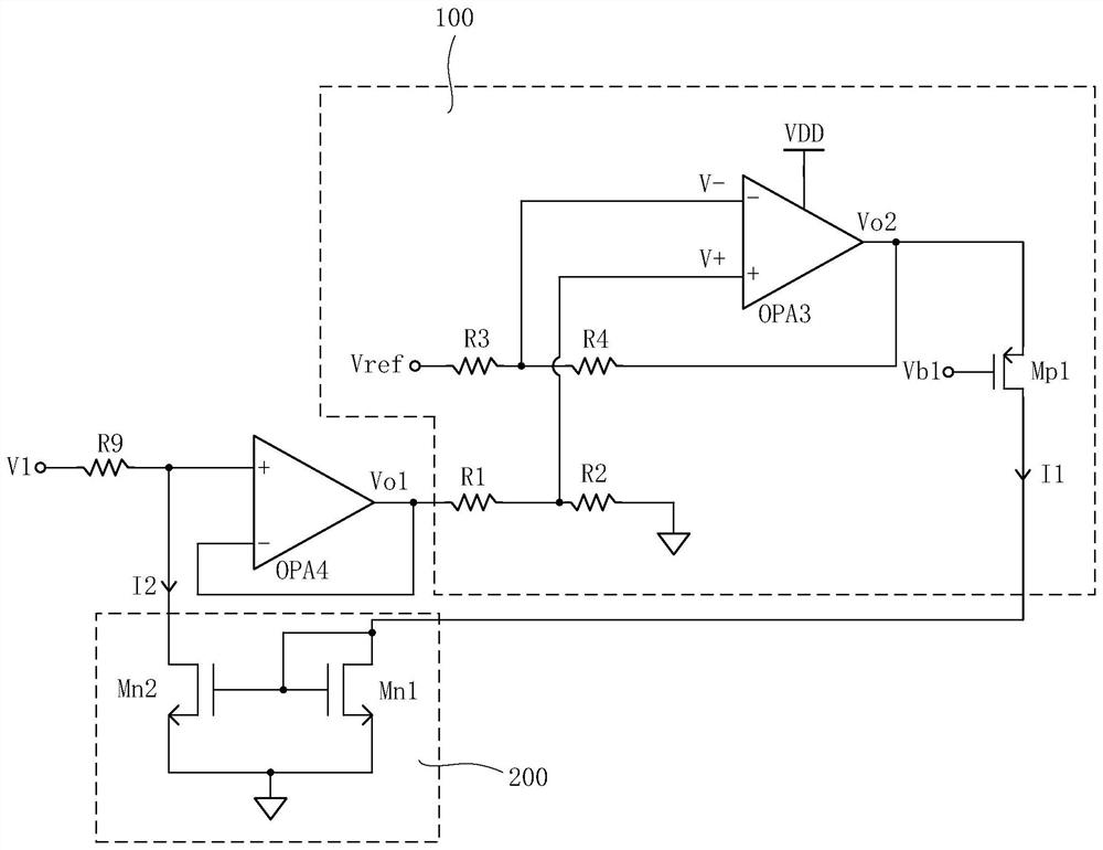
[0051] figure 2 A structural block diagram showing an adaptive supply voltage clamping circuit provided according to an embodiment of the present disclosure, image 3 A schematic circuit structure diagram of the adaptive power supply voltage clamping circuit provided according to the first embodiment of the present disclosure is shown.

[0052] like figure 2 As shown, in this embodiment, the adaptive power supply voltage clamping circuit includes: a clamping signal generation unit 100 and a voltage adjustment circuit 200 .

[0053] Wherein, the first input terminal of the clamping signal generating unit 100 receives the target voltage V1, the second input terminal receives the reference voltage Vref, and the third input terminal receives the power supply voltage VDD, the clamping signal generating unit 100 is used to monitor the target voltage V1, and When it is detected that the difference between the target voltage V1 and the voltage limit value corresponding to the target...

Embodiment 2

[0078] The circuit structure of the self-adaptive supply voltage clamping circuit provided by this embodiment is as follows Figure 4 shown.

[0079] Specifically, the adaptive power supply voltage clamping circuit provided in this embodiment is basically the same as that in the first embodiment above, so details are not repeated here.

[0080] The difference is that in this embodiment, the preset condition that is satisfied between the target voltage V1 monitored by the clamping signal generating unit 100 and the voltage limit value corresponding to the target voltage V1 is: the difference between the target voltage V1 and the voltage limit value Value is less than 0. That is to say, the adaptive supply voltage clamping circuit in the second embodiment of the present disclosure is to realize the pull-up clamping of the target voltage V1, that is, when the target voltage V1 in the circuit changes to less than the voltage limit value, the control The target voltage V1 is pull...


PUM


Abstract

The invention discloses a self-adaptive power supply voltage clamping circuit, and the circuit comprises a clamping signal generation unit which is used for monitoring a target voltage, and generating a clamping signal based on a reference voltage and a power supply voltage when monitoring that a difference value between the target voltage and a voltage limiting value meets a preset condition; the voltage adjusting unit is used for clamping the target voltage under the condition that the clamping signal is received, when the clamping signal generating unit generates the clamping signal based on the reference voltage and the power supply voltage, the clamping signal generating unit generates the clamping signal at different moments according to different power supply voltages under the condition that the reference voltage is not changed, and the clamping signal generating unit generates the target voltage according to the clamping signal. Therefore, the voltage limiting value of the target voltage changes along with the change of the power supply voltage. According to the self-adaptive power supply voltage clamping circuit, when the target voltage is clamped based on the voltage limiting value, the voltage limiting value can change along with the change of the power supply voltage, and the application range of the circuit is widened.

Description

technical field [0001] The invention relates to the technical field of integrated circuits, in particular to an adaptive power supply voltage clamping circuit. Background technique [0002] In many integrated circuits or circuit units, in order to prevent the voltage of a certain node in the circuit from exceeding the preset voltage value (that is, the voltage limit value), it is necessary to set a corresponding clamping circuit in the circuit to achieve the desired target voltage. Value clamping. [0003] Currently, existing clamping circuits such as figure 1 as shown, figure 1 A schematic circuit structure diagram of an existing clamping circuit is shown, and the clamping circuit includes an operational amplifier OPA1, an operational amplifier OPA2 and a transistor M1. The operational amplifier OPA1 is designed as a follower structure to convert the target voltage V1 into an output voltage Vo. The operational amplifier OPA2 is based on the reference voltage Vref and com...

Claims


Application Information

Patent Timeline
IPC IPC(8): G05F1/565
CPCG05F1/565
Inventor 许晶于翔
Owner SG MICRO
Why Eureka
Try Eureka