
Boiler coal slag clearing alarm method

A boiler and cinder technology, which is applied in the field of boiler cinder cleaning and alarming, can solve the problems of boiler economy and reliability reduction, and achieve the effect of improving self-adaptive ability, efficiency and detection efficiency

Active Publication Date: 2019-01-04
临沭县济才人力资源服务有限公司
View PDF10 Cites 0 Cited by
  • Summary
  • Abstract
  • Description
  • Claims
  • Application Information

AI Technical Summary

Problems solved by technology

The economy and reliability of boiler operation may be reduced when fuels with widely different characteristics are used

Method used


Image

  • Boiler coal slag clearing alarm method

Examples


Embodiment Construction

[0026] Embodiments of the present invention will be described in detail below with reference to the accompanying drawings.

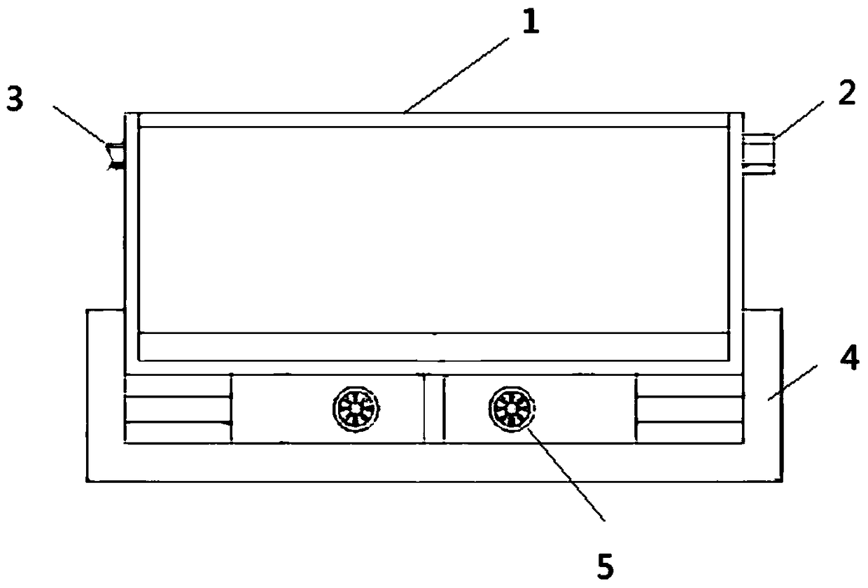
[0027] In order to overcome the current problems of difficult detection and cleaning of boiler cinders, the present invention builds a method for cleaning and alarming boiler cinders. Each briquette target and each cinder target are distinguished, and based on the recognition result of the number of cinder targets, it is determined whether to perform a boiler cinder cleaning alarm. The boiler cinder cleaning alarm platform automatically completes the above-mentioned processing in an electronic manner.

[0028] figure 1 It is a structural schematic diagram of a boiler cinder cleaning alarm platform according to an embodiment of the present invention, the platform includes a casing 1, a temperature control button 2, a water adding tank 3, a base 4, and left and right blast outlets 5;

[0029] The platform also includes:

[0030] The blowing operation swi...


PUM


Abstract

The invention relates to a boiler coal slag clearing arm method. The method comprises the following steps of: using a boiler coal slag clearing alarm platform and identifying each coal briquette objective and each coal slag objective from a plurality of coal body objectives based on appearance rule characteristics of coal briquettes; and determining whether to perform boiler coal slag clearing alarm or not based on identified results of quantity of the coal slag objectives.

Description

technical field [0001] The invention relates to the field of boiler control, in particular to a boiler cinder cleaning and alarm method. Background technique [0002] The overall structure of the boiler includes two parts: the boiler body, auxiliary equipment and safety devices. The furnace, drum, burner, water wall, superheater, economizer, air preheater, frame and furnace wall and other main components in the boiler constitute the core part of steam production, which is called the boiler body. The two most important components in the boiler body are the furnace and the drum. [0003] The furnace, also known as the combustion chamber, is a space for fuel combustion. The furnace that puts solid fuel on the grate and burns on the fire bed is called a bed furnace, also known as the fire bed furnace; the furnace that injects liquid, gas or powdered solid fuel into the fire chamber is called a chamber. Burning furnace, also known as fire chamber furnace; the air holds up the ...

Claims


Application Information

Patent Timeline
IPC IPC(8): F23J1/00F23J3/00H04N7/18
CPCF23J1/00F23J3/00F23J2700/001H04N7/183
Inventor 刘惠敏
Owner 临沭县济才人力资源服务有限公司
Learn More