Novel reactive power compensation cabinet based on electric energy quality control

A technology of power quality and power compensation, applied in reactive power compensation, reactive power adjustment/elimination/compensation, electrical components, etc., can solve problems such as inconvenient installation of power compensation devices, easy adhesion of dust to heat dissipation plates, and influence on the heat dissipation function of devices, etc. , to achieve the effect of convenient and convenient maintenance, increasing convenience and increasing convenient disassembly

Pending Publication Date: 2022-06-03
浙江南德电气制造有限公司
View PDF0 Cites 0 Cited by
  • Summary
  • Abstract
  • Description
  • Claims
  • Application Information

AI Technical Summary

Problems solved by technology

[0006] The invention provides a new type of non-power compensation cabinet based on power quality control, one of the purposes is to have the function of convenient disassembly and installation, and solve the problem that the internal structure of the traditional non-power compensation cabinet is complicated, and many devices often need to be installed inside, which is not convenient for power The installation of the compensation device brings inconvenience to the installers; another purpose is to solve the problem that the heat dissipation plate of the traditional powerless compensation cabinet is easy to stick to dust, resulting in a decrease in the heat dissipation effect, thereby affecting the heat dissipation function of the device. Achieve the function of cleaning dust and improve the cooling effect of the device

Method used


Image

  • Novel reactive power compensation cabinet based on electric energy quality control
  • Novel reactive power compensation cabinet based on electric energy quality control
  • Novel reactive power compensation cabinet based on electric energy quality control

Examples


Embodiment 1

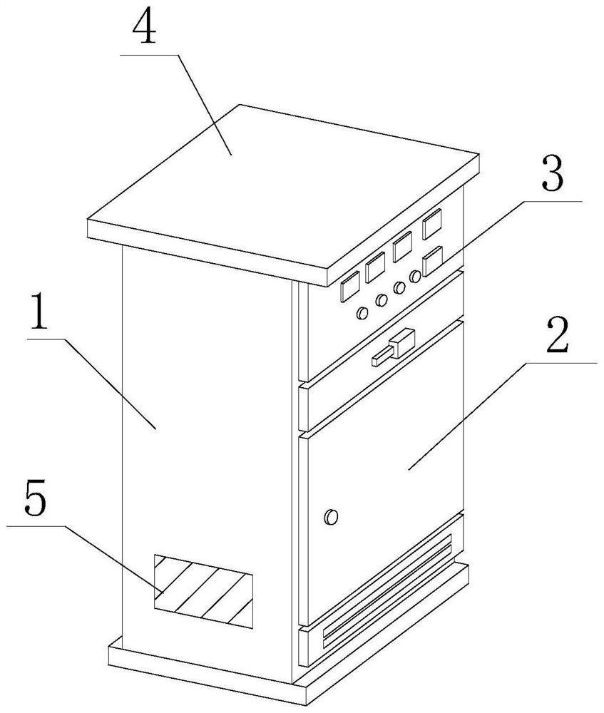
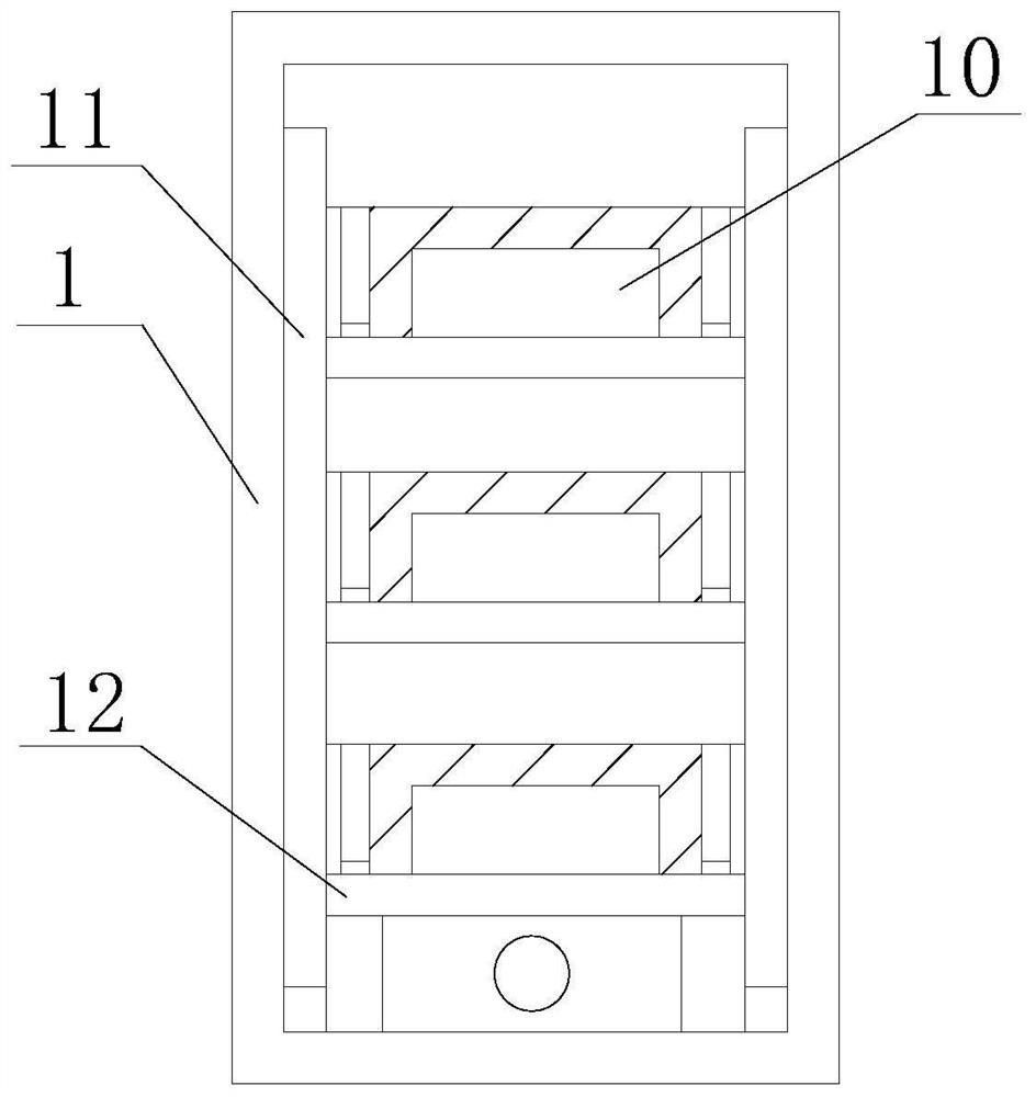
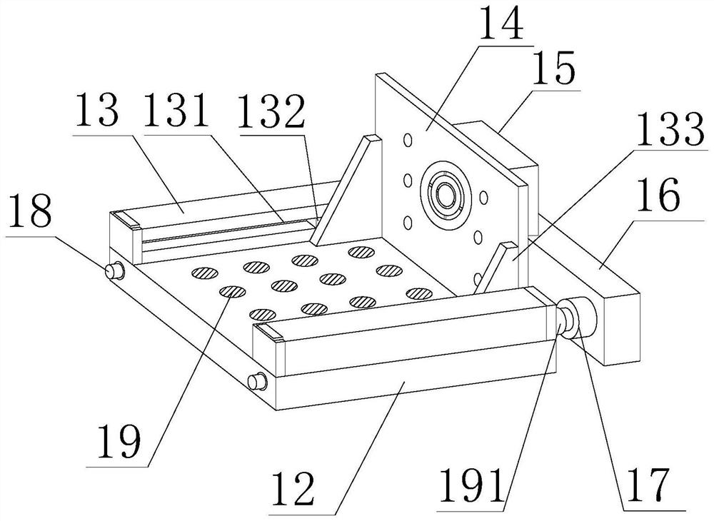
[0043] like Figure 1-8 As shown, the present invention provides a new type of non-power compensation cabinet based on power quality control, including a compensation cabinet body 1, a switch door 2, a control panel 3, a protective baffle 4 and a heat dissipation hole 5, and the side of the compensation cabinet body 1 is provided with a switch Door 2, the top of the switch door 2 is provided with a control panel 3, the top of the compensation cabinet body 1 is fixedly installed with a protective baffle 4, one side of the compensation cabinet body 1 is provided with a heat dissipation hole 5, and the interior of the compensation cabinet body 1 is fixed with a fixed Frame 11, the inner side of the fixed frame 11 is provided with a movable baffle 12, the interior of the movable baffle 12 is provided with electronic components 10, one side of the movable baffle 12 is provided with a telescopic rod 17, and the outer side of the telescopic rod 17 is provided with a clamping slot 171...

Embodiment 2

[0046] like Figure 1-8 As shown, on the basis of Embodiment 1, the present invention provides a technical solution: preferably, a pressing column 18 is arranged inside the moving baffle 12, and a limit block 191 is arranged at the other end of the pressing column 18, and the inner side of the limit block 191 It is arranged on the outer side of one end of the telescopic rod 17 .

[0047] Telescopic columns 192 are fixedly installed on both sides of the inner cavity of the limiting block 191 , and a clamping block 193 is fixedly installed at one end of the telescopic column 192 . There is a lift rod 194 , one end of the lift rod 194 is provided with a moving ring 195 , and the inner side of the moving ring 195 is provided at the outer side of the telescopic column 192 .

[0048] The other end of the moving ring 195 is provided with a folding rod 1951 .

[0049] In this embodiment, by squeezing and moving the pressing column 18 , the limiting block 191 is driven to be sleeved ...

Embodiment 3

[0051] like Figure 1-8 As shown, on the basis of Embodiment 1, the present invention provides a technical solution: preferably, a fixed column 13 is fixedly installed on the top of the movable baffle 12, and a chute 131 is opened on the inner side of the fixed column 13, and the inner side of the chute 131 is movable A slider 132 is installed.

[0052] A connecting inclined plate 133 is fixedly installed on the side of the slider 132 away from the chute 131 , a push plate 14 is fixedly connected to the side of the connecting inclined plate 133 , and a heat dissipation mechanism 15 is fixedly installed inside the push plate 14 .

[0053] In this embodiment, the sliding block 132 slides inside the chute 131, and then the sliding block 132 drives the connecting inclined plate 133 and the push plate 14 to slide, so as to push the electronic device to achieve the function of secondary pushing , it is convenient for the staff to carry out convenient disassembly, and the function o...


PUM


Abstract

The invention discloses a novel reactive power compensation cabinet based on electric energy quality control, and relates to the technical field of novel reactive power compensation cabinets, the novel reactive power compensation cabinet comprises a compensation cabinet main body, a switch door, a control panel, a protection baffle plate and heat dissipation holes, the switch door is arranged on the side surface of the compensation cabinet main body, and the control panel is arranged on the top of the switch door. The top of the compensation cabinet main body is fixedly provided with a protection baffle plate. According to the device, a telescopic rod telescopically moves to drive a movable baffle to be rapidly pushed out of a fixing frame, the rapid taking-out function is achieved, a worker can conveniently maintain the device, a sliding block slides in a sliding groove, then the sliding block drives a connecting inclined plate and a push plate to slide, an electronic instrument is pushed, and the secondary pushing function is achieved; according to the reactive power compensation cabinet, a worker can conveniently disassemble the reactive power compensation cabinet, the function of conveniently disassembling the reactive power compensation cabinet is added, the problems that a traditional reactive power compensation cabinet is complex in internal structure and inconvenient to disassemble the reactive power compensation cabinet are solved, the reactive power compensation cabinet can be conveniently disassembled, and the convenience of the reactive power compensation cabinet is improved.

Description

technical field [0001] The invention relates to the technical field of novel non-power compensation cabinets, in particular to a new type of non-power compensation cabinet based on power quality control. Background technique [0002] The main function of the reactive power compensation device is to improve the power factor of the load and the system, reduce the power loss of the equipment, stabilize the voltage, and improve the power supply quality. The non-power compensation device is in an indispensable and very important position in the power supply system. At present, non-power compensation devices are more and more widely used. When alternating current passes through pure resistance, electric energy is converted into heat energy, but when it passes through pure capacitive or pure inductive load, no work is done. That is to say, there is no power consumption, which is reactive power. Of course, the actual load cannot be a pure capacitive load or a pure inductive load. G...

Claims


Application Information

Patent Timeline
Patent Type & Authority Applications(China)
IPC IPC(8): H02B1/56H02B1/32H02B1/36H02J3/18B08B7/02
CPCH02B1/565H02B1/32H02B1/36H02J3/18B08B7/02Y02E40/30
Inventor 刘维城戴珏珺曾超
Owner 浙江南德电气制造有限公司
Why Eureka
Try Eureka