Receiving and transmitting co-located polarization laser radar system based on optical rotator

A technology of co-location of transceiver and lidar, applied in radio wave measurement systems, instruments, measurement devices, etc., can solve the cost and stability limitations of polarized lidar

Pending Publication Date: 2022-06-07
UNIV OF SCI & TECH OF CHINA
View PDF0 Cites 2 Cited by
  • Summary
  • Abstract
  • Description
  • Claims
  • Application Information

AI Technical Summary

Problems solved by technology

When receiving the signal beam, since the polarization beam splitter only allows reflection and transmission of light in a specific polarization direction, two detectors are requi

Method used


Image

  • Receiving and transmitting co-located polarization laser radar system based on optical rotator
  • Receiving and transmitting co-located polarization laser radar system based on optical rotator
  • Receiving and transmitting co-located polarization laser radar system based on optical rotator

Examples


Embodiment Construction

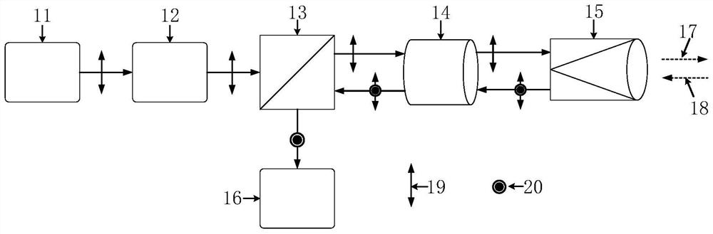
[0028] The technical solutions in the embodiments of the present invention will be clearly and completely described below with reference to the accompanying drawings in the embodiments of the present invention. Obviously, the described embodiments are only a part of the embodiments of the present invention, but not all of the embodiments. Based on the embodiments of the present invention, all other embodiments obtained by those of ordinary skill in the art without creative efforts shall fall within the protection scope of the present invention.

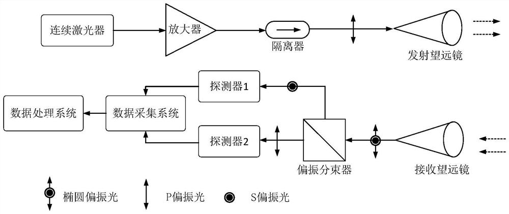
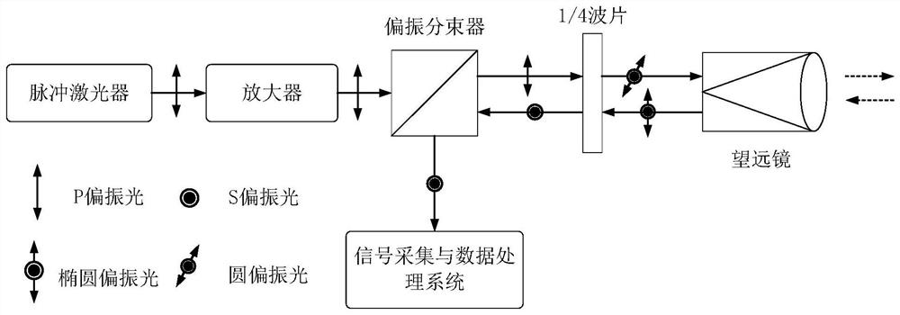
[0029] Based on the contents described in the background art, the structure of the transceiver system of the polarization laser radar can be divided into two types: the transceiver is separated and the transceiver is located together.

[0030] For the traditional transceiver split polarization lidar, the positions and angles of the transmitting telescope and the receiving telescope must be precisely adjusted to achieve better performan...


PUM


Abstract

The invention provides a polarization laser radar system with transmitting and receiving functions based on an optical rotator, and in the polarization laser radar system with transmitting and receiving functions, echo signal light obtained based on emergent signal light generated by a pulse laser comprises signal light in a parallel polarization state and signal light in a vertical polarization state. As the polarization beam splitter cannot reflect the signal light in the parallel polarization state, the polarization state of the echo signal light is adjusted by rotating the polarization plane of the echo signal light through the optical rotator, so that the optical rotator is in a working state and a non-working state respectively; all polarization states in echo signal light can be reflected to a signal detection and data processing system by the polarization beam splitter, so that the defect that the polarization beam splitter can only reflect signal light in one polarization direction is overcome; therefore, all polarization information of the polarized light in different directions in the echo signal light can be analyzed by the transmitting-receiving co-positioned polarized laser radar system, and the detection performance and the application range of the polarized laser radar are greatly expanded.

Description

technical field [0001] The present invention relates to the field of optoelectronic technology, and more particularly, to an optical rotator-based transceiver co-located polarization laser radar system. Background technique [0002] Since the development of polarized lidar, it has shown excellent performance in atmospheric detection, etc. Polarized lidar can effectively observe the spatiotemporal distribution and optical properties of non-spherical particles in the atmosphere, and deduce the atmospheric environment such as wind field, sand and dust. [0003] Due to the powerful detection performance of polarization lidar, its development is rapid and fruitful. For example, the dual-wavelength three-channel lidar deployed by the Meridian Project in my country can obtain atmospheric backscattered echo signals from near the ground to 110 km, and then invert parameters such as density, temperature, and sodium layer density in the middle and upper atmosphere. The lidar network b...

Claims


Application Information

Patent Timeline
IPC IPC(8): G01S7/483G01S7/481G01S17/95G01S17/88
CPCG01S7/483G01S7/481G01S17/95G01S17/88Y02A90/10
Inventor 王冲李鑫龙杨可欣薛向辉
Owner UNIV OF SCI & TECH OF CHINA
Why Eureka
Try Eureka