

Tool equipment for repairing parts of engineering machinery
A technology for construction machinery and tooling equipment, used in metal processing equipment, grinding machine parts, grinding workpiece supports, etc.
Active Publication Date: 2022-06-10
防城港瑞泰激光科技有限公司
View PDF11 Cites 2 Cited by
- Summary
- Abstract
- Description
- Claims
- Application Information
AI Technical Summary
Problems solved by technology
Aiming at the deficiencies of the prior art, the present invention provides a tooling equipment for the repair of engineering machinery parts, which has the advantages of metal debris and metal powder treatment, and solves the problem that the residue of metal debris and powder affects the follow-up of the hydraulic chuck. use problem
Method used
View moreImage
Smart ImageViewing Examples

Examples
Embodiment 1
Embodiment 2
Embodiment 3
Login to View More PUM
 Abstract
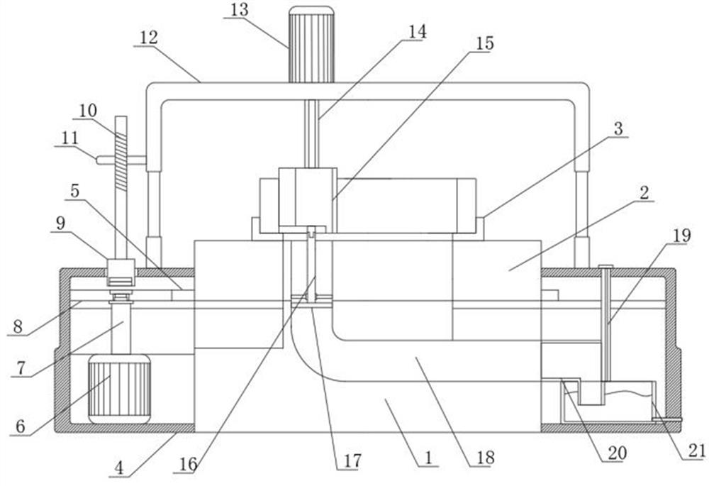
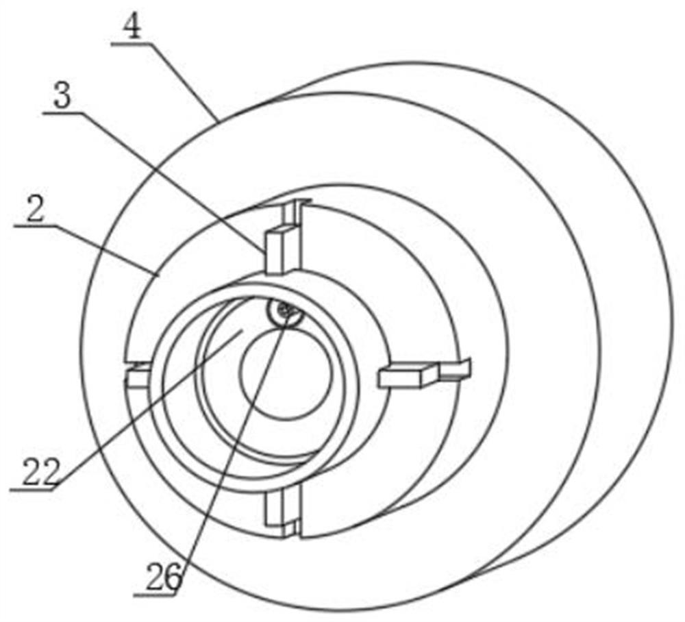
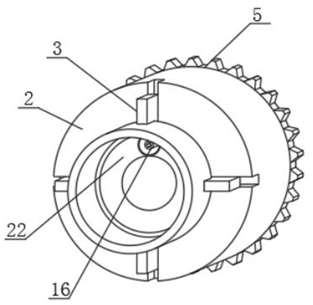
The invention relates to the technical field of bearing repairing, and discloses tool equipment for repairing engineering mechanical parts, which comprises a base, a hydraulic chuck and a transmission motor, the hydraulic chuck is rotatably connected to the top of the base, an inner shaft is sleeved in the hydraulic chuck, a clamping jaw is arranged at the top of the hydraulic chuck, and a clamping groove is formed in the top of the clamping jaw. The inner shaft is rotationally connected to the inner wall of the hydraulic chuck and fixedly connected to the base, a connecting rod is arranged in the inner shaft, and a connecting shaft is arranged at the output end of the transmission motor; when the grinding wheel roller conducts grinding, the butt joint shaft can be synchronously driven to rotate, rotation of the butt joint shaft drives the fan blades on the butt joint shaft to rotate, suction force can be generated when the fan blades rotate, the outer plate is arranged on the outer wall of the grinding wheel roller in a sleeving mode, and therefore the suction force can be generated at the gap between the grinding wheel roller and the outer plate through rotation of the fan blades; and metal scraps and powder generated by polishing are sucked into the inner shaft through suction force, and the situation that subsequent use of the hydraulic chuck is affected by the metal scraps and the powder is avoided.
Description
technical field [0001] The invention relates to the technical field of bearing repair, in particular to a tooling device used for repairing parts of engineering machinery. Background technique [0002] Some large mechanical equipment need to use large bearings. Due to their large size and high cost, these bearings often need to be repaired instead of replaced when they are damaged due to their large size and high cost. Now the repair of the inner ring of the bearing is often the The damaged inner ring is welded by electric welding, and then the welded part is polished by hand. [0003] For example, in the public document of a grinding device for large-scale bearing repair with the application number CN201921901044.6, a hydraulic chuck is used to clamp the inner ring of the bearing, and during the grinding process of the grinding wheel roller, the metal debris and powder produced It will fall on the hydraulic chuck, which will affect the subsequent use of the hydraulic chuck...
Claims
Login to View More Application Information
Patent Timeline
 Patent Type & AuthorityApplications(China)
IPC IPC(8): B24B5/08B24B55/06B24B47/22B24B41/06B24B47/12
CPCB24B5/08B24B55/06B24B47/22B24B41/067B24B47/12Y02P70/10
Inventor王留红
Owner防城港瑞泰激光科技有限公司