Gas turbine inlet air temperature control system

A technology of intake air temperature and control system, which is applied in the direction of gas turbine devices, refrigerators, mechanical equipment, etc., can solve the problems that the intake air temperature of gas turbines cannot be adjusted, the adjustment method is single, and can only be increased or decreased, so as to achieve the summer peak The effect of running, increasing the intake air temperature, and improving efficiency

Pending Publication Date: 2022-06-17
HUANENG BEIJING CO GENERATION
0 Cites 0 Cited by

AI-Extracted Technical Summary

Problems solved by technology

[0005] To sum up, the gas turbine intake air temperature needs to be adjusted according to the external working environment temperature. Single, can only increase or decrea...

Method used

Further, the gas-steam combined cycle unit also includes a second pump body 35, the water inlet end of the second pump body 35 is connected with the drain end of the condenser 31, and the second pump body The water outlet end of the body 35 is connected with the water inlet end of the waste heat boiler 29 . Preferably, the second pump body 35 is a booster pump. The condensed water formed in the condenser 31 is pressurized by the second pump body 35, and then sent to the waste heat boiler 29, which ensures the smooth delivery of the condensed water and improves the stability of the system.
In summary, this specification discloses a control system for gas turbine intake air temperature, which adopts the method of setting an air heat exchanger at the inlet of the gas turbine compressor to adjust the intake air temperature of the gas turbine, and through a plurality of valves Controlling the switching of cold and hot media achieves the purpose of raising or lowering the intake temperature of the gas turbine according to the actual operating conditions, and meets the different needs of the unit under different operating conditions. Under the condition of high ambient temperature and high load in summer, the cold medium is introduced into the air heat exchanger to cool the air at the gas turbine inlet, r...

Abstract

The embodiment of the invention provides a gas turbine inlet air temperature control system which comprises a gas-steam combined cycle unit and a heat exchange mechanism, the heat exchange mechanism comprises an air heat exchanger, and an air outlet of the air heat exchanger communicates with an air inlet of an air compressor of a gas turbine; the water inlet end of the air heat exchanger is connected with a heat exchange water inlet pipeline, and a third valve is arranged on the heat exchange water inlet pipeline and used for controlling water circulation in the heat exchange water inlet pipeline. The water outlet end of the air heat exchanger is connected with a heat exchange water outlet pipeline, and a fourth valve is arranged on the heat exchange water outlet pipeline and used for controlling water circulation in the heat exchange water outlet pipeline. A cooling water inlet pipe is led out of the heat exchange water inlet pipeline to convey cooling media, and a first heating water inlet pipe and a second heating water inlet pipe are led out to convey heating media. Switching of cold and hot media of the air heat exchanger is controlled through the multiple valves, the purpose of increasing or reducing the gas inlet temperature of the gas turbine according to the actual operation condition is achieved, and different requirements of a unit are met.

Application Domain

Technology Topic

Image

  • Gas turbine inlet air temperature control system

Examples

  • Experimental program(1)

Example Embodiment

[0034]下面将结合本说明书实施例中的附图,对本说明书实施例中的技术方案进行清楚、完整地描述,显然,所描述的实施例仅仅是本发明一部分实施例,而不是全部的实施例。基于本发明中的实施例,本领域普通技术人员在没有付出创造性劳动前提下所获得的所有其他实施例,都属于本发明保护的范围。
[0035]需要说明的是,本说明书实施例及附图中的术语“包括”和“具有”以及它们任何变形,意图在于覆盖不排他的包含。例如包含了一系列步骤或单元的过程、方法、系统、产品或设备没有限定于已列出的步骤或单元,而是可选地还包括没有列出的步骤或单元,或可选地还包括对于这些过程、方法、产品或设备固有的其它步骤或单元。
[0036]本说明书实施例公开了一种燃机进气温度的控制系统。以下分别进行详细说明。
[0037]燃气轮机作为一种容积式动力机械设备,其输出功率与进口空气的质量流量有关,当进口空气温度下降时,空气的密度增大,进口空气的质量流量随之增大,则燃机的输出功率和效率也提高,因此可以得出结论:在“冷”的环境下,燃气轮机会有更大的出力,故在高温环境下可通过降低进气温度来提高燃机出力。在部分负荷下,如果在负荷不变的情况下提高进气温度,透平前温度就会提高(前提是未进入温控),进而提高燃机效率,燃机以部分负荷运行时,压气机的进气质量流量为定值,提升燃机进气温度会降低进气空气密度,从而提高进气体积流量,迫使压气机IGV角度开大,从而减少IGV内空气流动的节流损失,改善压气机运行状况,达到节能和提高效率的目的。因此,在不同运行情况下,燃机对其进气温度的要求有所不同,在高温大负荷工况下,需要通过降低燃机的进气温度以提高燃机出力,而在部分负荷工况下,则需要通过提高燃机的进气温度以提高燃机效率。
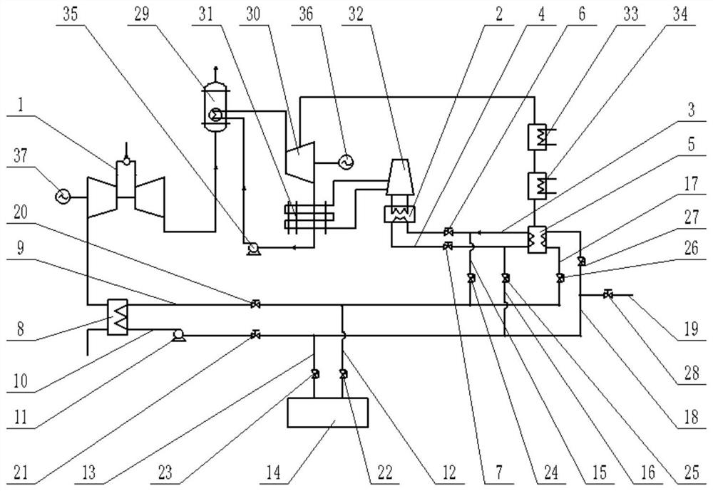
[0038]本发明实施例提供了一种燃机进气温度的控制系统,如图1所示,所述控制系统包括:燃气–蒸汽联合循环机组和换热机构,其中,所述燃气–蒸汽联合循环机组包括:燃气轮机1、闭冷水换热器2、闭冷水回水管3、闭冷水供水管4、二级疏水冷却器5,所述换热机构包括空气换热器8、换热进水管道9、换热出水管道10、第一泵体11、冷却进水管12、冷却出水管13、溴化锂装置14、第一加热进水管15、第一加热出水管16、第二加热进水管17、第二加热出水管18、引水管19。
[0039]具体的,所述闭冷水换热器2的进水口连接有闭冷水回水管3,所述闭冷水回水管3上安装有第一阀门6,用于控制所述闭冷水回水管3内的闭冷水回水流通;所述闭冷水换热器2的出水口连接有闭冷水供水管4,所述闭冷水供水管4上安装有第二阀门7,用于控制所述闭冷水供水管4内的闭冷水流通;所述二级疏水冷却器5的进水口与所述闭冷水供水管4相连通,所述二级疏水冷却器5的出水口与所述闭冷水回水管3相连通;
[0040]所述空气换热器8的出气口与所述燃气轮机1的压气机进气口相连通;所述空气换热器8的进水端连接所述换热进水管道9,所述换热进水管道9上设置有第三阀门20,用于控制所述换热进水管道9内的水流通;所述空气换热器8的出水端连接有所述换热出水管道10,所述换热出水管道10上设置有第四阀门21,用于控制所述换热出水管道10内的水流通;所述第一泵体11安装在所述换热出水管道10上;所述换热进水管道9上引出一路所述冷却进水管12与所述溴化锂装置14的出水口相连通,所述冷却进水管12上设置有第五阀门22,用于控制所述冷却进水管12内的空调冷水流通;所述换热出水管道10上引出一路所述冷却出水管13与所述溴化锂装置14的进水口相连通,所述冷却出水管13上设置有第六阀门23,用于控制所述冷却出水管13内的水流通;所述换热进水管道9上引出一路所述第一加热进水管15与所述闭冷水回水管3相连通,且所述第一加热进水管15设置于所述第一阀门6与所述二级疏水冷却器5之间;所述第一加热进水管15上安装有第七阀门24,用于控制所述第一加热进水管15内的水流通;所述换热出水管道10上引出一路所述第一加热出水管16与所述闭冷水供水管4相连通,且所述第一加热出水管16设置于所述第二阀门7与所述二级疏水冷却器5之间;所述第一加热出水管16上安装有第八阀门25,用于控制所述第一加热出水管16内的水流通;所述换热进水管道9上引出一路所述第二加热进水管17与所述二级疏水冷却器5的出水口相连通,所述第二加热进水管17上设置有第九阀门26,用于控制所述第二加热进水管17内的水流通;所述换热出水管道10上引出一路所述第二加热出水管18与所述二级疏水冷却器5的进水口相连通,所述第二加热出水管18上设置有第十阀门27,用于控制所述第二加热出水管18内的水流通;所述第二加热出水管18上连接有所述引水管19,所述引水管19上安装有第十一阀门28,用于控制所述引水管19内的中介水流通。
[0041]采用在燃气轮机1的压气机进气口处设置空气换热器8,并通过第一阀门6、第二阀门7、第三阀门20、第四阀门21、第五阀门22、第六阀门23、第七阀门24、第八阀门25、第九阀门26、第十阀门27、第十一阀门28,多个阀门控制空气换热器8冷热介质的切换,从而满足机组在实际运行状况下的不同需求。
[0042]在本发明实施例中,换热进水管道9作为空气换热器8的总进水管道,用于向空气换热器8中输送换热介质,第三阀门20接通或阻断换热进水管道9内的水流通,换热出水管道10作为空气换热器8的总出水管道,用于将在空气换热器8内换热后的换热介质输送至空气换热器8外,第四阀门21接通或阻断换热出水管道10内的水流通。冷却进水管12、冷却出水管13为空气换热器8的冷介质输送管道,并分别通过第五阀门22、第六阀门23控制各自管道内的冷介质流通,第一加热进水管15、第一加热出水管16为空气换热器8闭冷水回水热介质来源的输送管道,并通过第一阀门6、第二阀门7、第七阀门24、第八阀门25阻断或接通向空气换热器8中闭冷水回水热源的输送,而第二加热进水管17、第二加热出水管18为空气换热器8热网二级疏水热介质来源的输送管道,并通过第九阀门26、第十阀门27、第十一阀门28阻断或接通向空气换热器8中热网二级疏水热介质中介水的输送。
[0043]采用空调冷水作为空气换热器8的冷介质来源,不仅能够降低燃机进气温度以达到增加燃机出力的目的,且利用现有的制冷系统,减少了额外投资成本。同时,本实施例采用闭冷水回水、热网二级疏水作为空气换热器8的热介质来源,使用低品位热源,解决了现有技术中压气机抽气方式采用高品位热源导致经济效益较差的问题,降低了机组的冷源损失,且达到了提高燃机进气温度以提高机组效率的目的。
[0044]其中,本实施例所提供的燃机进气温度的控制系统的具体控制过程如下:
[0045]当不投运所述空气换热器8时,将所述第三阀门20、第四阀门21、第五阀门22、第六阀门23、第七阀门24、第八阀门25、第九阀门26、第十阀门27、第十一阀门28关闭,所述第一阀门6、第二阀门7开启,闭冷水从所述闭冷水换热器2流出,经所述闭冷水供水管4流入所述二级疏水冷却器5中,在所述二级疏水冷却器5内对热网二级疏水进行冷却,换热后的闭冷水经所述闭冷水回水管3输送回所述闭冷水换热器2内;
[0046]当需要降低燃机进气温度时,将所述第七阀门24、第八阀门25、第九阀门26、第十阀门27、第十一阀门28关闭,所述第一阀门6、第二阀门7、第三阀门20、第四阀门21、第五阀门22、第六阀门23开启,所述二级疏水冷却器5内的热网二级疏水由所述闭冷水换热器2流出的闭冷水冷却,所述溴化锂装置14所产生的空调冷水经所述冷却进水管12、换热进水管道9输送至所述空气换热器8内,空调冷水在所述空气换热器8内对空气进行冷却,冷却后的空气通过所述燃气轮机1的压气机进气口进入所述燃气轮机1内,换热后的空调冷水在所述第一泵体11的作用下依次流经所述换热出水管道10、冷却出水管13,输送回所述溴化锂装置14内;
[0047]当需要提高燃机进气温度时,将所述第一阀门6、第二阀门7、第五阀门22、第六阀门23、第七阀门24、第八阀门25关闭,所述第三阀门20、第四阀门21、第九阀门26、第十阀门27、第十一阀门28开启,中介水由所述引水管19引入,并经所述第二加热出水管18输送至所述二级疏水冷却器5中,在所述二级疏水冷却器5内对热网二级疏水进行冷却,换热后升温的中介水经所述第二加热进水管17、换热进水管道9输送至所述空气换热器8中,在所述空气换热器8内对空气进行加热,加热后的空气通过所述燃气轮机1的压气机进气口进入所述燃气轮机1内,换热后的中介水在所述第一泵体11的作用下通过所述换热出水管道10、第二加热出水管18输送至所述二级疏水冷却器5内,对所述二级疏水冷却器5内的热网二级疏水进行冷却,进行循环热交换;或者,
[0048]当需要提高燃机进气温度时,将所述第一阀门6、第二阀门7、第五阀门22、第六阀门23、第九阀门26、第十阀门27、第十一阀门28关闭,所述第三阀门20、第四阀门21、第七阀门24、第八阀门25开启,所述闭冷水回水管3内的闭冷水回水通过所述第一加热进水管15、换热进水管道9输送至所述空气换热器8中,在所述空气换热器8内与空气进行热交换,换热后升温的空气通过所述燃气轮机1的压气机进气口进入所述燃气轮机1内,换热后冷却的闭冷水回水在所述第一泵体11的作用下通过所述换热出水管道10、第一加热出水管16输送至所述闭冷水供水管4,再次进入闭冷水循环系统循环。
[0049]由上述可知,本实施例通过多个阀门的控制实现了向空气换热器8内输送冷热介质的切换,优选的,所述第一阀门6、第二阀门7、第三阀门20、第四阀门21、第五阀门22、第六阀门23、第七阀门24、第八阀门25、第九阀门26、第十阀门27、第十一阀门28均为截止阀。此外,所述空气换热器8优选板式空气换热器。
[0050]从而实现了根据实际运行情况提高或降低燃机进气温度的目的,满足了机组的不同需求。在夏季环境温度较高大负荷工况下,向空气换热器内通入冷介质,对燃机进气口的空气进行冷却,降低燃机进气温度,保持夏季燃机出力,实现夏季顶峰运行,提高燃机电厂负荷能力。在部分负荷的情况下,向空气换热器内通入热介质,对燃机进气口的空气进行加热,提高燃机进气温度,提高燃机透平前温度,从而提升机组效率。
[0051]在一个具体的实施例中,所述燃气–蒸汽联合循环机组还包括余热锅炉29、蒸汽轮机30、凝汽器31、冷却塔32、热网加热器33以及一级疏水冷却器34,其中,所述燃气轮机1的出汽端与所述余热锅炉29的进汽端相连通,所述余热锅炉29的出汽端连通所述蒸汽轮机30的进汽端,所述蒸汽轮机30的出汽端连通所述热网加热器33的进汽端,所述热网加热器33的出汽端与所述一级疏水冷却器34的进水端相连通,所述一级疏水冷却器34的出水端连通所述二级疏水冷却器5的进水端,所述蒸汽轮机30的排汽端与所述凝汽器31的进汽端相连通,所述凝汽器31的排水端连通所述余热锅炉29的进水端,所述冷却塔32分别与所述凝汽器31、闭冷水换热器2相连通。
[0052]在空气换热器8内进行热交换后的空气从压气机进气口进入燃气轮机1中的压气机内,在其内进行压缩,然后流向燃气轮机1的燃烧室,与燃烧室喷入的燃料混合后燃烧,成为高温燃气,随即流入燃气轮机1的透平中膨胀做功,之后,仍具有较高能量的高温气体被输送至余热锅炉29内,在余热锅炉29中将水加热形成蒸汽,所产生的蒸汽从余热锅炉29的出汽端流入蒸汽轮机30内,推动蒸汽轮机30作业。从蒸汽轮机30排汽端排出的气体进入凝汽器31中冷却形成凝结水,之后,由凝汽器31的排水端排出并输送至余热锅炉29的进水端,作为余热锅炉29所需的水源。
[0053]进一步的,所述燃气–蒸汽联合循环机组还包括第二泵体35,所述第二泵体35的进水端与所述凝汽器31的排水端相连,所述第二泵体35的出水端与所述余热锅炉29的进水端相连。优选的,所述第二泵体35均为增压泵。在凝汽器31内形成的凝结水由第二泵体35进行增压,继而被输送至余热锅炉29中,保证了凝结水的顺利输送,提高了系统的稳定性。
[0054]冷却塔32分别与凝汽器31、闭冷水换热器2相连通,为凝汽器31、闭冷水换热器2提供冷却水源,在凝汽器31内对蒸汽轮机30的排汽进行冷却,使其形成凝结水,在闭冷水换热器2内对闭冷水回水进行冷却,使冷却后的闭冷水重新输送至闭冷水循环系统中进行循环,冷却塔32将携带废热的冷却水在塔内与空气进行热交换,使废热传输给空气并散入大气。
[0055]本实施例中的燃气–蒸汽联合循环机组为热网供热,蒸汽轮机30所排出的高热量气体作为热网的热源,从蒸汽轮机30的出汽端排出,并通过热网加热器33的进汽端进入热网加热器33内,为所需地区进行供热,同时,为了减少疏水排挤低压抽汽而引起的热损失,将热网加热器33所排出的水依次经由一级疏水冷却器34、二级疏水冷却器5进行冷却后再加热处理。
[0056]在本发明实施例中,本燃机进气温度的控制系统采用多轴布置方案,所述燃气–蒸汽联合循环机组还包括第一发电机36和第二发电机37,所述蒸汽轮机30与所述第一发电机36同轴连接,驱动所述第一发电机36发电;所述燃气轮机1的压气机与所述第二发电机37同轴连接,驱动所述第二发电机37发电。详细的,从余热锅炉29输送至蒸汽轮机30内的蒸汽推动蒸汽轮机4作业,从而驱动第一发电机36发电;高温燃气进入燃气轮机1的透平中膨胀做功,推动透平叶轮带着压气机叶轮一起旋转,第二发电机37与燃气轮机1的压气机同轴,进而驱动第二发电机37发电。
[0057]需要注意并理解的是,本实施例仅示出了机组多轴布置方案,但是本控制系统并不仅限于多轴布置方案,还可根据需求将本控制系统应用在单轴布置方案上。
[0058]综上所述,本说明书公开一种燃机进气温度的控制系统,采用在燃机压气机入口设置空气换热器的方式,调节燃机的进气温度,并通过多个阀门控制冷热介质的切换,实现了根据实际运行情况提高或降低燃机进气温度的目的,满足了机组不同运行状况下的不同需求。在夏季环境温度较高大负荷工况下,向空气换热器内通入冷介质,对燃机进气口的空气进行冷却,降低燃机进气温度,保持夏季燃机出力,实现夏季顶峰运行,提高燃机电厂负荷能力。而在部分负荷的情况下,向空气换热器内通入热介质,对燃机进气口的空气进行加热,提高燃机进气温度,提高燃机透平前温度,从而提升机组效率。
[0059]本领域普通技术人员可以理解:附图只是一个实施例的示意图,附图中的模块或流程并不一定是实施本发明所必须的。
[0060]本领域普通技术人员可以理解:实施例中的装置中的模块可以按照实施例描述分布于实施例的装置中,也可以进行相应变化位于不同于本实施例的一个或多个装置中。上述实施例的模块可以合并为一个模块,也可以进一步拆分成多个子模块。
[0061]最后应说明的是:以上实施例仅用以说明本发明的技术方案,而非对其限制;尽管参照前述实施例对本发明进行了详细的说明,本领域的普通技术人员应当理解:其依然可以对前述实施例所记载的技术方案进行修改,或者对其中部分技术特征进行等同替换;而这些修改或者替换,并不使相应技术方案的本质脱离本发明实施例技术方案的精神和范围。

PUM

no PUM

Description & Claims & Application Information

We can also present the details of the Description, Claims and Application information to help users get a comprehensive understanding of the technical details of the patent, such as background art, summary of invention, brief description of drawings, description of embodiments, and other original content. On the other hand, users can also determine the specific scope of protection of the technology through the list of claims; as well as understand the changes in the life cycle of the technology with the presentation of the patent timeline. Login to view more.

Similar technology patents

Reinforced bed frame

ActiveUS20200146460A1Improve load capacityImprove efficiencyBedstandsEngineeringStructural engineering
Owner:NEW TEC INTEGRATION (XIAMEN) CO LTD

Classification and recommendation of technical efficacy words

  • Improve load capacity
  • Increase intake air temperature

Method of reinforcing a bridge

InactiveCN101091023AImprove load capacityDamage minimizationBridge erection/assemblyBridge strengtheningEngineeringClosed cavity
Owner:INTELLIGENT ENG BAHAMAS

Reinforced bed frame

ActiveUS20200146460A1Improve load capacityImprove efficiencyBedstandsEngineeringStructural engineering
Owner:NEW TEC INTEGRATION (XIAMEN) CO LTD

Engine crankcase ventilation system and method

InactiveCN111997710AIncrease intake air temperatureReduce the rate of oil agingNon-fuel substance addition to fuelExhaust gas recirculationAutomotive engineeringMotor oil
Owner:KUNMING YUNNEI POWER +1

Air inlet heating control method and device, electronic equipment and computer storage medium

PendingCN114396346AIncrease intake air temperatureGood for starting performanceMachines/enginesThermal treatment of fuelOperating temperatureIntake pressure
Owner:WEICHAI POWER CO LTD

Far-infrared heating sauna room

Owner:WUHU SAUNAKING ELECTRONICS TECH CO LTD

Sauna room with massage function

InactiveCN108743323AGood relaxing effectIncrease intake air temperatureDiagnosticsDevices for pressing relfex pointsExhaust gasMassage
Owner:WUHU SAUNAKING ELECTRONICS TECH CO LTD
Why Eureka
Try Eureka