Rotary wing helicopter

A helicopter and rotor technology, applied in the field of rotor helicopters, can solve problems such as waste of engine power, low lift efficiency, torsional vibration and operation response lag, and achieve the effects of increasing payload, increasing safety and reliability, and reducing weight

Inactive Publication Date: 2006-10-18
刘昌喆
View PDF0 Cites 0 Cited by
  • Summary
  • Abstract
  • Description
  • Claims
  • Application Information

AI Technical Summary

Problems solved by technology

[0003] The lift effect makes the rotor of the cantilever beam structure upturned, and its rotation track is an inverted umbrella surface, so that the efficiency of generating lift is low, and a large part of the power of the engine is wasted.
The direction contr

Method used


Image

  • Rotary wing helicopter
  • Rotary wing helicopter

Examples


Embodiment Construction

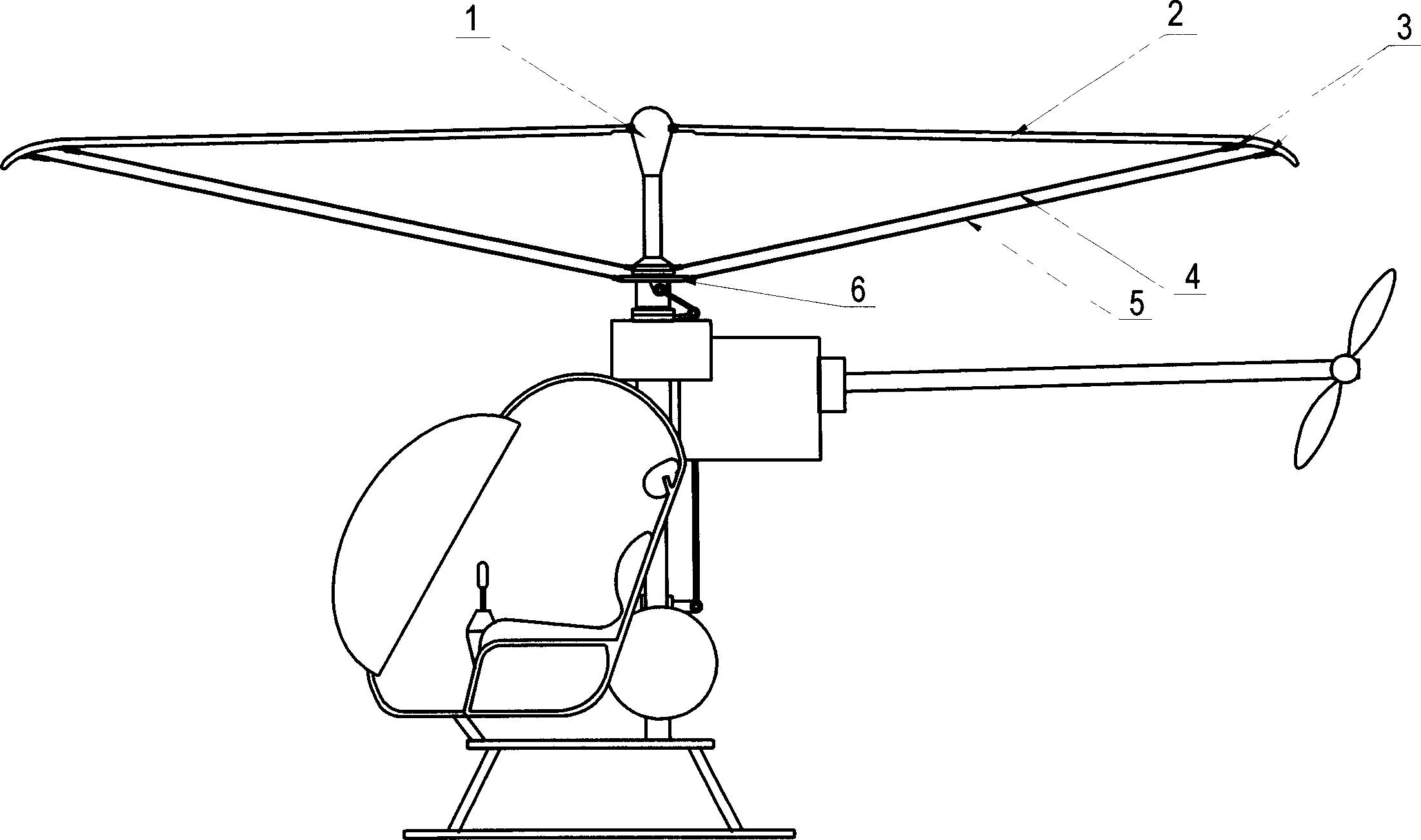
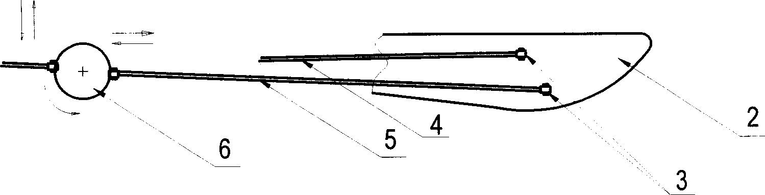
[0016] see figure 1 and figure 2 , is a preferred embodiment of the present invention, the helicopter of the canopy rotor track of the present invention has rotor 2 and rotating propeller hub 1, and the root of rotor 2 is hinged on the upper end of propeller hub 1, and at the outer end of rotor 2 and paddle At least one connecting piece 4 is connected between the hubs 1, the connecting piece 4 can be a tension cable or a connecting rod, and its two ends are respectively hinged on the outer end of the rotor 2 and the lower end of the propeller hub 1, during work, the rotor 2 and connecting piece 4 rotate together with the propeller hub 1.

[0017] A control ring 6 is also arranged below the above-mentioned propeller hub 1. The control ring 6 is a translational control ring, which rotates synchronously with the propeller hub 1 and can translate on the vertical plane of the rotating shaft at the same time, so that the rotor 2 can move in the whole The lift force on each sector...


PUM


Abstract

The present invention relates to one kind of rotating wing helicopter. The rotating wing helicopter has at least one connecting piece hinged between the outer end of the rotating wing and the lower part of the oar hub for the rotating wing and the oar hub to rotate simultaneously; one control ring set below the oar hub; and one subsidiary connecting piece connected between the outer end of the rotating wing and the control ring. During flying, the rotating wings form one umbrella shaped rotating locus to converge the airflow pressing to below the rotating wings, raise the lift force of the rotating wings and increase effective load. The load force moment is resolved homogeneously into tensions without concentrated stress, resulting in light structure. The subsidiary connecting piece is used in regulating the lift angle of the rotating wing to control the flying direction, and its tension acts directly onto the outer end of the rotating wings to avoid torsional vibration and reaction lagging.

Description

【Technical field】 [0001] The invention relates to a rotor helicopter, in particular to a helicopter with an umbrella surface rotor track. 【Background technique】 [0002] At present, the rotors of helicopters are all cantilever beam structures, and their wingspans are all designed to be quite long in order to obtain sufficient lift. The severe moment load condition on the normal plane makes the rotor root, flapping hinge and rotating propeller hub necessarily designed to be strong and heavy, so that the effective load is reduced and the manufacturing cost is increased. [0003] The lift effect makes the rotor of the cantilever beam structure upturned, and its rotation track is an inverted umbrella surface, so that the efficiency of generating lift is low, and a large part of the power of the engine is wasted. The direction control mechanism of the existing helicopter acts on the root of the inner end of the rotor, and the most effective part of the aerodynamic force is the o...

Claims


Application Information

Patent Timeline
IPC IPC(8): B64C27/32
CPCB64C27/06A63H27/12
Inventor 刘昌喆
Owner 刘昌喆
Why Eureka
Try Eureka