Sliding bearing assembly

A technology for sliding bearings and components, applied in the field of sliding bearing components, to achieve the effects of improving load capacity, simple installation, and saving structural space

Active Publication Date: 2021-04-09
MIBA SINTER AUSTRIA
View PDF16 Cites 0 Cited by
  • Summary
  • Abstract
  • Description
  • Claims
  • Application Information

AI Technical Summary

Problems solved by technology

[0005] At this point there is a proble

Method used


Image

  • Sliding bearing assembly
  • Sliding bearing assembly
  • Sliding bearing assembly

Examples


Embodiment Construction

[0025] At the outset, it should be pointed out that in the different described embodiments, the same parts are provided with the same reference symbols or the same component designations, wherein the disclosure content contained in the entire description can be transferred to the reference symbols with the same reference symbols. Or on the same part with the same component name. The positional specifications selected in the description, such as top, bottom, sideways, etc., also refer to the directly described and illustrated figures and these positional specifications are transferred to the new position in the event of a position change.

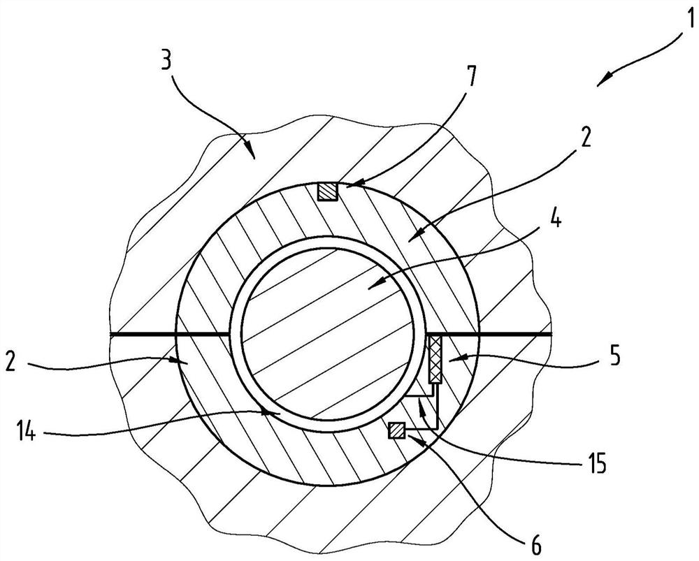
[0026] exist figure 1 A detail of a plain bearing assembly 1 is shown in .

[0027] The plain bearing assembly comprises at least one plain bearing element 2 . In the illustrated embodiment, two plain bearing elements 2 are shown, which have the shape of a so-called half-shell. However, there is also the possibility that the plain bearing...


PUM


Abstract

The invention relates to a sliding bearing assembly (1) comprising at least one sliding bearing element (2) which is situated in a bearing socket (3), the bearing socket (3) being part of a bearing structure, and the bearing structure having at least one sensor (5) which is connected: to a data transfer device (6) for the transfer of data, in particular wirelessly, to a receiver of the data; and to an energy generation device (7) for the autonomous supply of electrical energy to the sensor (5) and/or the data transfer device (6). The energy generation device (7) has at least one piezo element (8) which is compressively preloaded, or the energy generation device (7) is the sensor (5).

Description

technical field [0001] The invention relates to a plain bearing assembly comprising at least one plain bearing element arranged in a bearing receptacle which is part of a bearing structure and which has at least one sensor, which is connected to a data transmission device for in particular wireless data transmission to a data receiver, and the sliding bearing assembly has an energy generating device for feeding the sensor and / or the data transmission device is self-sufficiently powered. [0002] Furthermore, the invention relates to a method for monitoring a plain bearing element in a plain bearing receptacle of a plain bearing assembly with at least one sensor, with which a measured value is detected and transmitted to a data transmission device, In order to transmit data, in particular wirelessly, to a data receiver and to generate electrical energy for the sensor and / or the data transmission device via the movement of the plain bearing element or the plain bearing assembl...

Claims


Application Information

Patent Timeline
IPC IPC(8): F16C41/00F16C17/24G01M13/04G01L5/00F16C17/02
CPCF02D2400/14F16C41/008F16C2233/00G01L5/0019G01M13/045H02N2/186H04Q2209/886F16C41/007F16C41/004G01M13/04F16C17/24F16C17/02F16C2202/36F16C2223/60
Inventor G·哈格尔K·哈姆达德S·沙尔梅纳
Owner MIBA SINTER AUSTRIA
Why Eureka
Try Eureka