Single-bus wiring structure

A wiring structure and single busbar technology, which is applied to AC network circuits, electrical components, reactive power compensation, etc., can solve problems such as not being able to meet the needs of users for electricity, and achieve the goal of improving power supply capacity, reducing circuit loss, and increasing load capacity. Effect

Pending Publication Date: 2020-08-07
SHENZHEN POWER SUPPLY PLANNING DESIGN INST
0 Cites 2 Cited by

AI-Extracted Technical Summary

Problems solved by technology

[0002] At present, with the continuous growth of the total power load and density in various cities, the function of the 220kV power grid is gradually transformed...

Method used

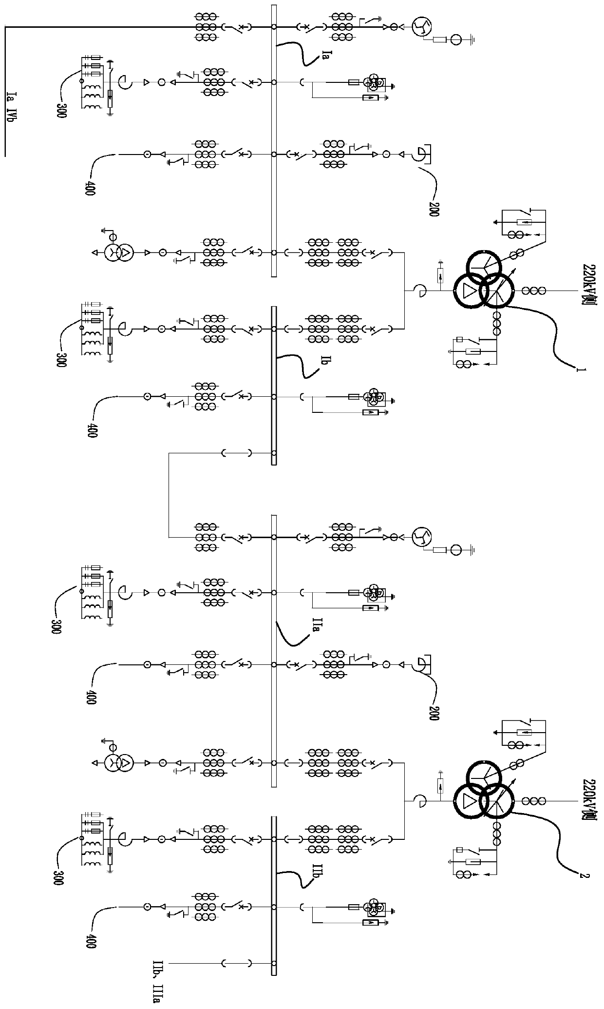
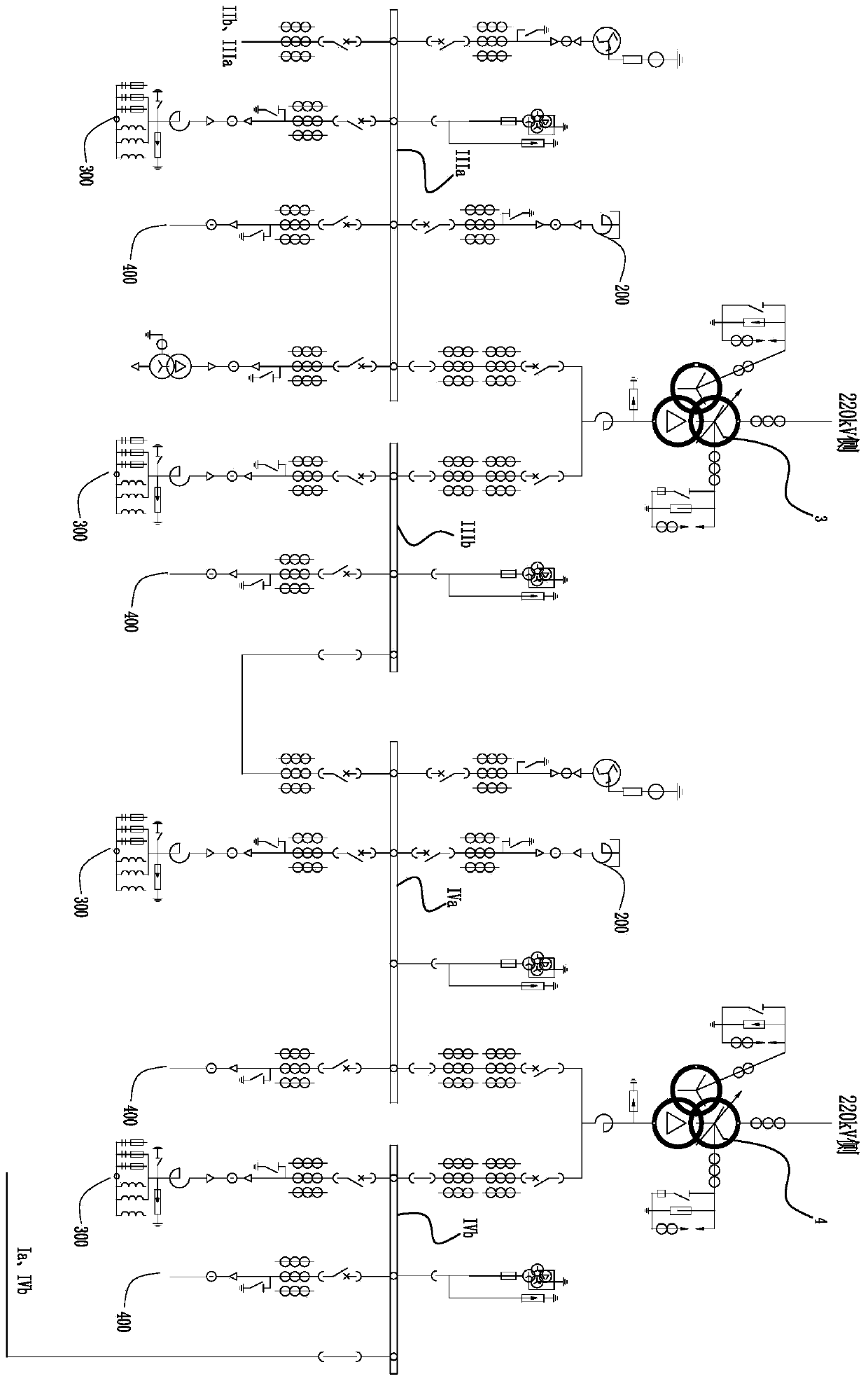
Above-mentioned busbar voltage is 10kV, with reference to Fig. 2A-2B, is the wiring diagram of single busbar wiring structure in the embodiment of the present invention, understandable Fig. 2B is the continuation of Fig. 2A, and its disconnection terminal uses IIb, IIIa It is indicated that the connection between the fourth sub-bus and the fifth sub-bus is disconnected. Similarly, the terminals at the disconnection are denoted by Ⅰa and Ⅳb as the connection between the first sub-bus and the eighth sub-bus. Therefore, Fig. 2A and Fig. After the 2B connection is the complete drawing. In this embodiment, the wiring is carried out in the form of single busbar, double-section four-section busbar, more specifically one busbar, and the busbar corresponding to each main transformer is divided into two branch busbar sections, and then four main busbars are formed. The final busbar form of the eight-section busbar of the transformer. At this time, each main transformer can withstand 10 outgoing lines. Each 10kV main transformer adopts double-arm incoming lines to form two sections of 10kV busbars, which are respectively the first sub-bus Ia and the second sub-bus Ia. The second sub-bus Ib section, the third sub-bus IIa, the fourth sub-bus IIb, the fifth sub-bus IIIa, the sixth sub-bus IIIb, the seventh sub-bus IVa, and the eighth sub-bus IVb, each section of sub-bus has 5 circuits of 10kV Outlet, that is, each main transformer has 10 outlet circuits, and four main transformers have a total of 40 10kV outlet circuits. At this time, each main transformer has a load of about 69MVA, and the four main transformers have a load of about 276MVA. The load capacity Strong, it...

Abstract

The invention discloses a single-bus wiring structure, and relates to the field of power supply and distribution. The single-bus wiring structure comprises a bus, which is used for connecting the output side of a main transformer, and comprises multiple sections of sub-buses, the multiple sections of sub-buses are connected in sequence, and the first section of sub-bus and the last section of sub-bus are connected to form an annular structure. According to the invention, the defects of low load capacity of the low-voltage side of the main transformer and unreliable power grid power supply areovercome, the load capacity of the low-voltage side of the main transformer can be improved, and the power grid power supply reliability is improved.

Application Domain

Emergency protective circuit arrangementsReactive power adjustment/elimination/compensation +3

Technology Topic

Power gridLow load +5

Image

  • Single-bus wiring structure
  • Single-bus wiring structure
  • Single-bus wiring structure

Examples

  • Experimental program(1)

Example Embodiment

[0032] In the following, the concept of the present invention and the technical effects produced by it will be clearly and completely described in conjunction with the embodiments to fully understand the purpose, features and effects of the present invention. Obviously, the described embodiments are only a part of the embodiments of the present invention, rather than all of them. Based on the embodiments of the present invention, other embodiments obtained by those skilled in the art without creative work belong to The scope of protection of the present invention.
[0033] In the description of the present invention, if an orientation description is involved, such as "up", "down", "front", "rear", "left", "right", etc., the orientation or positional relationship indicated is based on the drawings. The orientation or positional relationship is only for the convenience of describing the present invention and simplifying the description, rather than indicating or implying that the device or element referred to must have a specific orientation, be constructed and operated in a specific orientation, and therefore cannot be understood as a limitation of the present invention . If a feature is called "set", "fixed", "connected" or "installed" on another feature, it can be directly set, fixed, or connected to another feature, or indirectly set, fixed, or connected , Installed on another feature.
[0034] In the description of the embodiments of the present invention, if it refers to "several", it means more than one, if it refers to "multiple", it means more than two, if it refers to "greater than", "less than", "more than ", should be understood as not including the number, if it involves "above", "below", and "within", it should be understood as including the number. If it involves “first” and “second”, it should be understood as used to distinguish technical features, but cannot be understood as indicating or implying relative importance or implicitly indicating the number of the indicated technical features or implicitly indicating the indicated The sequence of technical features.
[0035] In one embodiment of the present invention, refer to figure 1 The single busbar wiring structure includes: a busbar, which is used to connect the output side of the main transformer. The above-mentioned busbar includes multiple sub-busbars 100, which are connected in sequence. The first sub-busbar 100 and the last sub-busbar 100 are connected to form a ring. N segments can be selected according to the actual scene, so that the failure of any sub-bus bar will not affect the power supply of the entire load side.
[0036] Reference Figure 2A-Figure 2B , The output sides of the main transformer 1, the main transformer 2, the main transformer 3, and the main transformer 4 are the medium voltage and/or low voltage output sides, and the sub bus includes the first sub bus Ia, the second sub bus Ib, and the third sub bus. Bus IIa, fourth sub-bus IIb, fifth sub-bus IIIa, sixth sub-bus IIIb, seventh sub-bus IVa, eighth sub-bus IVb, the above-mentioned first sub-bus Ia, second sub-bus Ib, and third sub-bus IIa, the fourth sub bus IIb, the fifth sub bus IIIa, the sixth sub bus IIIb, the seventh sub bus IVa, and the eighth sub bus IVb are connected in sequence, and the first sub bus Ia is also connected to the eighth sub bus IVb to form a ring.
[0037] Specifically, this embodiment takes four main transformers as an example for illustration. At least one bus bar is connected to the low-voltage side of the four main transformers, and at least one bus bar is divided into at least eight sub-buses. The eight sub-buses are the first sub-bus Ia, the second sub-bus Ib, the third sub-bus IIa, and the fourth sub-bus. Bus IIb, fifth sub-bus IIIa, sixth sub-bus IIIb, seventh sub-bus IVa, eighth sub-bus IVb, among them, the first sub-bus Ia, the second sub-bus Ib, the third sub-bus IIa, and the fourth sub-bus Bus IIb, fifth sub-bus IIIa, sixth sub-bus IIIb, seventh sub-bus IVa, and eighth sub-bus IVb are connected end to end to form a ring structure.
[0038] The above bus voltage is 10kV, refer to Figure 2A-2B , Is the wiring diagram of the single busbar wiring structure in the embodiment of the present invention, understandable Figure 2B for Figure 2A Continuation of the continuation, the disconnection terminals are represented by Ⅱb and Ⅲa as the connection of the fourth sub-bus and the fifth sub-bus. Similarly, the disconnected terminals are represented by Ia and Ⅳb as the first sub-bus and the first sub-bus. The eight-sub bus connection is disconnected, so Figure 2A with Figure 2B After connection, the complete picture is shown. In this embodiment, a single busbar, double-segmented four-segment busbar is used for wiring. More specifically, it is a busbar. The busbar corresponding to each main transformer is divided into two branch busbar segments, and then four main busbars are formed. The final busbar form of the eight-segment busbar of the transformer. At this time, each main transformer can withstand 10 outgoing circuits, and each main transformer 10kV adopts double-arm incoming lines, each forming two 10kV busbars, which are the first sub-bus Ia and the first sub-bus respectively. Second sub-bus section Ib, third sub-bus IIa, fourth sub-bus IIb, fifth sub-bus IIIa, sixth sub-bus IIIb, seventh sub-bus IVa, eighth sub-bus IVb, each section of sub-bus has 5 times 10kV Outgoing line, that is, each main transformer has 10 outgoing circuits, and 4 main transformers have a total of 40 10kV outgoing circuits. At this time, each main transformer has a load of about 69MVA, and the four main transformers have a load of about 276MVA, with load capacity. Strong, it is understandable that the above-mentioned main transformer load is calculated based on three-phase electricity as an example, and the above-mentioned main transformer load calculation formula is as follows:
[0039]
[0040] Among them, P is the main transformer load, U is the busbar voltage, I is the maximum current that the main transformer can pass, and COSφ is the power factor. Its values ​​are respectively, U is 10kV, and I is the maximum current that the main transformer circuit breaker can work normally 4000A , COSφ takes the maximum value 1, and the obtained value P is 69.28MVA. In this embodiment, the integer part 69MVA is selected for description, and the value range of COSφ is 0.9≤COSφ≤1.
[0041] It is understandable that the voltage connected to the high-voltage side of the main transformer 1, the main transformer 2, the main transformer 3, and the main transformer 4 is 220kV, and each main transformer is connected in parallel with a set of reactors 200, in which the first sub-bus Ia and the third sub-bus Bus IIa, fifth sub-bus IIIa, and seventh sub-bus IVa are respectively connected to two sets of capacitors 300, and second sub-bus Ib, fourth sub-bus IIb, sixth sub-bus IIIb, and eighth sub-bus IVb are respectively connected to 3 sets of capacitors 300, each bus bar is connected to 5 outgoing circuits 400, but the number of groups or outgoing circuits of the connected capacitor 300 is limited according to the actual practical scenario of this embodiment, but it is not limited to the above number, it can be based on the actual situation Make your own settings.
[0042] Among them, the main function of the main transformer shunt reactor 200 in this embodiment is:
[0043] 1. Reduce the increase in power frequency voltage.
[0044] Understandably, UHV transmission lines generally have long distances, up to hundreds of kilometers. As the line uses split conductors, the line-to-phase and ground-to-ground capacitances are large. After connecting a parallel reactor on the ultra-high voltage transmission line, the rise of the power frequency voltage at the end of the line can be significantly reduced.
[0045] 2. Reduce the operating overvoltage.
[0046] The operating overvoltage is generated by the opening and closing operations of the circuit breaker. When the circuit breaker is used to switch on or cut off some electrical components in the system, the operating overvoltage will appear on the break of the circuit breaker, which is often caused by the increase in the power frequency voltage. The power frequency voltage rises due to load rejection and single-phase grounding. When the circuit breaker cuts the ground fault or recloses after the ground fault is removed, it will cause the system operation overvoltage and the power frequency voltage rise Superimpose with the operating overvoltage to make the operating overvoltage higher. Therefore, the degree of power frequency voltage rise directly affects the amplitude of the operating overvoltage. After installing the parallel reactor, the increase of the power frequency voltage is limited, thereby reducing the amplitude of the operating overvoltage.
[0047] When the no-load circuit with shunt reactor is opened, the residual charge on the broken circuit is introduced into the earth along the reactor, so that the recovery voltage on the breaker of the circuit breaker rises slowly from zero, which greatly reduces the weight of the breaker. The possibility of burning, therefore also reduces the operating overvoltage.
[0048] 3. Conducive to single-phase reclosing.
[0049] In order to improve operation reliability, single-phase automatic reclosing is often used in ultra-high voltage power grids, that is, when a single-phase grounding fault occurs in the line, the line is immediately disconnected, and the phase is reclosed after the arc at the fault is extinguished. Due to the large capacitance and inductance between UHV transmission lines, after the fault phase disconnects the short-circuit current, the non-fault phase power supply (power neutral point is grounded) will continue to provide arc current to the fault point through these capacitance and inductance, making it difficult to arc at the fault. Extinguished.
[0050] In another embodiment of the present invention, between the first sub-bus bar Ia and the second sub-bus bar Ib, between the third sub-bus bar IIa and the fourth sub-bus bar IIb, and the fifth sub-bus bar IIIa and the sixth sub-bus bar IIIb Between the seventh sub-bus bar IVa and the eighth sub-bus bar IVb are all connected by the first connecting member, between the second sub-bus bar and the third sub-bus bar, between the fourth sub-bus bar and the fifth sub-bus bar, and between the sixth sub-bus bar and the sixth sub-bus bar. The sub-bus bar and the seventh sub-bus bar are both connected by a second connecting member, wherein the first connecting member is connected to the output side of the main transformer.
[0051] More specifically, the first connecting component includes at least two circuit breakers and at least two current transformers, and the second connecting component includes at least one circuit breaker and at least one current transformer.
[0052] Specifically, between the first sub-bus Ia and the second sub-bus Ib, between the third sub-bus IIa and the fourth sub-bus IIb, between the fifth sub-bus IIIa and the sixth sub-bus IIIb, and the seventh sub-bus The bus IVa and the eighth sub-bus IVb are both connected by at least two circuit breakers 500 and at least two current transformers 600. Among them, the second sub-bus IIa and the third sub-bus Ib, the fourth sub-bus IIb and The fifth sub-bus bar IIIa, the sixth sub-bus bar IIIb and the seventh sub-bus bar IVa, and the eighth sub-bus bar IVb and the first sub-bus bar Ia are connected by at least one circuit breaker and at least one current transformer.
[0053] Specifically, the reason for the combined use of the current transformer and the circuit breaker is to be able to timely determine the faults that do not meet the power requirements, and disconnect the circuit breaker in time to avoid the occurrence of major power failures and improve the reliability of the power system. It is understandable that the installation positions and installation quantities of the current transformers and circuit breakers can be set according to actual application scenarios, and are not limited to the wiring positions installed in this embodiment.
[0054] The above-mentioned circuit breaker is an isolating circuit breaker. The reason why the circuit breaker in this embodiment adopts an isolating circuit breaker is that the isolating circuit breaker can significantly improve the reliability of the substation. In addition, during the use of the isolation circuit breaker, regardless of whether there is abrasion on the contacts or whether the arc extinguishing produces decomposition by-products, it must meet the requirements of isolation characteristics.
[0055] More specifically, an isolating circuit breaker uses a combination of an isolating switch and a circuit breaker so that the circuit breaker can be regularly maintained. As the number of faults and maintenance of circuit breakers is greatly reduced, the isolation function is more used for maintenance of overhead lines and power transformers. The maintenance amount of the circuit breaker is reduced, and the reliability is improved, and the isolation circuit breaker combines the switch and the isolation function in one device, which reduces the footprint of the substation and improves the utilization rate.
[0056] The above-mentioned first sub-bus bar Ia, second sub-bus bar Ib, third sub-bus bar IIa, fourth sub-bus bar IIb, fifth sub-bus bar IIIa, sixth sub-bus bar IIIb, seventh sub-bus bar IVa, and eighth sub-bus bar IVb are respectively connected There are multiple outgoing circuits. It is understandable that in the power system, the bus bar connects the current-carrying branch circuits in the power distribution device together, and plays the role of collecting, distributing and transmitting electric energy. It is the total power used by the power station or substation to transmit electric energy. The wire and outgoing circuit are the above-mentioned branch circuits on the bus bar, which play a role in distributing and transmitting electric energy. The circuit is set according to the electric energy required by the load and the maximum carrying capacity of the transformer.
[0057] Each of the above-mentioned first sub-bus Ia, second sub-bus Ib, third sub-bus IIa, fourth sub-bus IIb, fifth sub-bus IIIa, sixth sub-bus IIIb, seventh sub-bus IVa, and eighth sub-bus IVb The sub-bus bars are all connected to multiple sets of capacitors 300, where the capacitor 300 is a reactive power compensation capacitor. In this embodiment, the sub-bus bar is connected to the capacitor 300, which is similar to a capacitive load on the bus bar and absorbs the capacitive reactive power of the system. It is equivalent to the parallel capacitor sending inductive reactive power to the system, so the parallel capacitor can provide inductive reactive power to the system, the power factor of the system operation, increase the voltage level of the bus bar at the receiving end, and reduce the transmission of inductive reactive power on the line. The voltage and power loss are improved, so the transmission capacity of the line is improved, that is, it can compensate for reactive power, improve power factor, improve voltage quality, and reduce line loss.
[0058] In the wiring method of the above-mentioned embodiment, there are 4 main transformers in the whole station, and each 10kV main transformer adopts double-arm incoming lines, each forming two sections of 10kV bus bars, namely the first sub-bus Ia, the second sub-bus Ib, and the third sub-bus. Bus IIa, fourth sub-bus IIb, fifth sub-bus IIIa, sixth sub-bus IIIb, seventh sub-bus IVa, and eighth sub-bus IVb, among the above eight sections of 10kV bus, any one main transformer or one section of 10kV bus Loss of power will not affect the loss of other 10kV busbars and meet the requirements of power supply safety regulations; and any main transformer loses power, while a section of 10kV busbar also loses power, or any two main transformers lose power, or any two busbars Power loss will not affect the power loss of other 10kV buses, and it also meets the power system safety criteria, such as the N-1 criteria.
[0059] Specifically, for example, the above four main transformers are defined as main transformer 1, main transformer 2, main transformer 3, and main transformer 4. When main transformer 1 loses power, sub-bus Ia is powered by sub-bus IVb, and sub-bus Ib Power supply via sub-bus IIa, according to the single-bus connection structure in this embodiment, will not affect the power failure of the 10kV bus of the main transformer 1 and other bus power failures. More specifically, for example, the sub-bus IIa loses power while the main transformer 1 fails. , Then the section I bus is supplied by the section Ia of the bus and the section IVb of the bus, which will not affect the power outage of other bus bars; for example, if any two bus bars lose power, they can be powered by the second arm branch of the corresponding main transformer without affecting Other busbar power failures can also meet the power system safety criteria, such as the N-2 criterion.
[0060] The beneficial effect of the patent of the invention is to change the 10kV side of the main transformer 1, main transformer 2, main transformer 3, and main transformer 4 in the traditional 220kV substation to adopt single bus double segment four-segment bus connection, and each main transformer carries 10 There are two circuits outgoing, and the 4 main transformers are connected by a unit without outgoing wiring. The total number of load-bearing circuits is only 30 circuits. In this embodiment, each sub-bus configuration is 5 circuits, and the eight-section sub-bus configuration can be 40 circuits. On this basis, more circuits can be appropriately configured, and the number of 10kV outgoing circuits in 220kV substations has been increased, thereby improving the load supply capacity of the low-voltage side of the main transformer and improving the reliability of power supply to the power grid.
[0061] The embodiments of the present invention are described in detail above with reference to the accompanying drawings. However, the present invention is not limited to the above-mentioned embodiments. Within the scope of knowledge possessed by a person of ordinary skill in the art, various modifications can be made without departing from the purpose of the present invention. Variety. In addition, the embodiments of the present invention and the features in the embodiments can be combined with each other if there is no conflict.

PUM

no PUM

Description & Claims & Application Information

We can also present the details of the Description, Claims and Application information to help users get a comprehensive understanding of the technical details of the patent, such as background art, summary of invention, brief description of drawings, description of embodiments, and other original content. On the other hand, users can also determine the specific scope of protection of the technology through the list of claims; as well as understand the changes in the life cycle of the technology with the presentation of the patent timeline. Login to view more.

Similar technology patents

Vehicle steering apparatus

InactiveUS20110000737A1improve reliabilitylarge mount area
Owner:JTEKT CORP

Distributed storage system

InactiveUS20100115078A1improve reliabilityminimize increase in management workload
Owner:SKY PERFECT JSAT CORPORATION

Dual-Dielectric MIM Capacitors for System-on-Chip Applications

ActiveUS20100213572A1reduced process step and complexityimprove reliability
Owner:TAIWAN SEMICON MFG CO LTD

Gas turbine inlet air temperature control system

PendingCN114635797AImprove load capacityincrease intake air temperature
Owner:HUANENG BEIJING CO GENERATION

Method of reinforcing a bridge

InactiveCN101091023AImprove load capacitydamage minimization
Owner:INTELLIGENT ENG BAHAMAS

Flip chip semiconductor package and fabrication method thereof

ActiveUS20100230810A1improve soldering strengthimprove reliability
Owner:NEPES CO LTD

Classification and recommendation of technical efficacy words

  • Improve reliability
  • Improve load capacity

Organic light emitting diode display

ActiveUS20070008268A1improve reliability
Owner:LG DISPLAY CO LTD

Method and apparatus for correcting errors in memory device

ActiveUS20120151294A1improve reliability
Owner:SAMSUNG ELECTRONICS CO LTD

Multiple branch predictions

ActiveUS20050268075A1improve reliabilityfacilitate availability
Owner:ORACLE INT CORP

Method of reinforcing a bridge

InactiveCN101091023AImprove load capacitydamage minimization
Owner:INTELLIGENT ENG BAHAMAS

Gas turbine inlet air temperature control system

PendingCN114635797AImprove load capacityincrease intake air temperature
Owner:HUANENG BEIJING CO GENERATION
Why Eureka
Try Eureka