Radial thrust acquisition mechanism and thrust vector measurement device and method

A technology of radial thrust and thrust vector, applied in the field of rockets, can solve problems such as inability to realize radial measurement and inability to obtain direction information of engine combined thrust

Pending Publication Date: 2022-06-17
BEIHANG UNIV
View PDF11 Cites 0 Cited by
  • Summary
  • Abstract
  • Description
  • Claims
  • Application Information

AI Technical Summary

Problems solved by technology

[0004] The purpose of this application is to provide a radial thrust acquisition mechanism, a thrust vector measurement device and method, to solve the problem in the prior art that the radial measurement cannot be realized and the direction information of the combined thrust of the engine cannot be obtained to a certain extent. technical problem

Method used


Image

  • Radial thrust acquisition mechanism and thrust vector measurement device and method
  • Radial thrust acquisition mechanism and thrust vector measurement device and method
  • Radial thrust acquisition mechanism and thrust vector measurement device and method

Examples


Embodiment 1

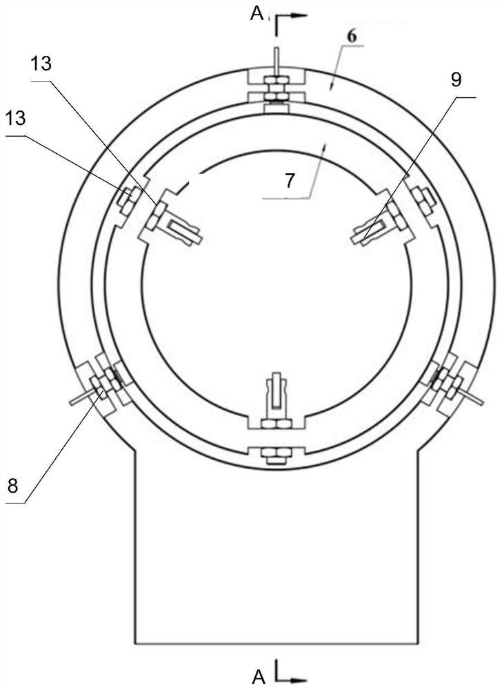
[0071] see Figure 1 to Figure 6 As shown, the embodiment of the present application provides a radial thrust acquisition mechanism for detecting the radial thrust of the component to be tested, especially the radial thrust of the rocket engine 12 .

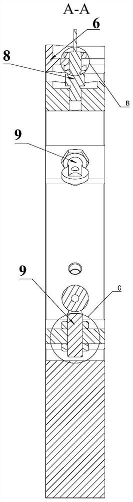
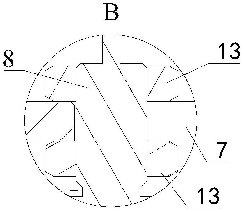
[0072] The radial thrust collection mechanism provided in this embodiment for the thrust vector measurement device includes a first fixed frame, a first moving frame, a pulley 9 and a radial tension pressure sensor 8 .

[0073] Hereinafter, the above-mentioned components of the radial thrust collecting mechanism will be described in detail.

[0074] see Figure 1 to Figure 6 , in the optional solution of this embodiment, the first fixed frame is provided with an installation hole, the first movable frame is arranged in the installation hole, the first movable frame is annular, and the inner space of the first movable frame forms a predetermined cylindrical area, and the predetermined cylindrical area is formed. The cylindrical ...

Embodiment 2

[0088] The second embodiment provides a thrust vector measurement device, which includes the radial thrust collecting mechanism in the first embodiment, and the technical features of the radial thrust collecting mechanism disclosed in the first embodiment are also applicable to this embodiment. The technical features of a disclosed radial thrust collecting mechanism will not be described again.

[0089] combine Figure 1 to Figure 6 and see Figure 7 to Figure 10 As shown, the thrust vector measurement device provided in this embodiment is used for vector measurement of the thrust of the rocket engine 12 .

[0090] The rocket motor 12 includes a head, a body, and a tail arranged in sequence along its own axis. The rocket engine thrust vector measurement device includes a working platform 1, an axial thrust acquisition mechanism and at least one radial thrust acquisition mechanism.

[0091] Hereinafter, the above-mentioned components of the rocket engine 12 will be described...


PUM


Abstract

The invention relates to the technical field of rockets, in particular to a radial thrust collecting mechanism and a thrust vector measuring device and method. The radial thrust acquisition mechanism comprises a first fixed frame, a first movable frame, a pulley and a radial tension and pressure sensor; the first movable frame is arranged in the mounting hole of the first fixed frame and forms an annular interval; a preset cylinder area is formed in the annular first movable frame, at least three pulleys are connected with the first movable frame and arranged around the preset cylinder area, and the sliding direction is the axial direction so as to clamp a to-be-detected component in the preset cylinder area; the radial tension and pressure sensor can strain in the radial direction and is connected with the first fixed frame and the first movable frame, so that the first movable frame can move in the radial direction. The thrust vector measuring device comprises the radial thrust acquisition mechanism. The thrust vector measurement adopts the thrust vector measurement device. According to the radial thrust acquisition mechanism, the thrust vector measurement device and the thrust vector measurement method, independent measurement of the radial thrust and measurement of the combined thrust direction of the engine are realized.

Description

technical field [0001] The present application relates to the field of rocket technology, and in particular, to a radial thrust acquisition mechanism, a thrust vector measurement device and a method. Background technique [0002] In the field of thrust measurement of liquid rocket engines, to achieve vector measurement of engine thrust (that is, to measure thrust magnitude and thrust direction at the same time), it is often necessary to use a six-component force sensor. The six-component force sensor can realize the measurement of single-point and multi-directional force, and the vector measurement effect can be achieved by using multiple sensors in combination, but the six-component force sensor needs to be customized, has poor versatility, and is easily damaged. [0003] When using the pull pressure sensor for thrust measurement, only axial measurement can be achieved at present, but radial measurement cannot be achieved, and the direction information of the combined thrus...

Claims


Application Information

Patent Timeline
Patent Type & Authority Applications(China)
IPC IPC(8): G01M15/02G01M15/14G01L5/00
CPCG01M15/02G01M15/14G01L5/0038
Inventor 俞南嘉龚昊杰周闯安山
Owner BEIHANG UNIV
Why Eureka
Try Eureka