
Engine hanger for tilting ducted aircraft

An engine pylon and engine technology, which is applied to the power plant, aircraft parts, wings and other directions of the aircraft, can solve problems such as low efficiency, and achieve the effects of improving safety, improving flutter characteristics, and improving aircraft range and payload.

Pending Publication Date: 2022-06-21
宗宁
View PDF2 Cites 0 Cited by
  • Summary
  • Abstract
  • Description
  • Claims
  • Application Information

AI Technical Summary

Problems solved by technology

This existing technology removes the traditional wing structure, the engine is fixedly installed in the non-deflectable duct, and the vertical take-off and landing relies on the flaps to guide the deflection of the airflow. The efficiency of deflection propulsion is very low, and it does not involve the pylon structure of the engine

Method used


Image

  • Engine hanger for tilting ducted aircraft
  • Engine hanger for tilting ducted aircraft
  • Engine hanger for tilting ducted aircraft

Examples


Embodiment Construction

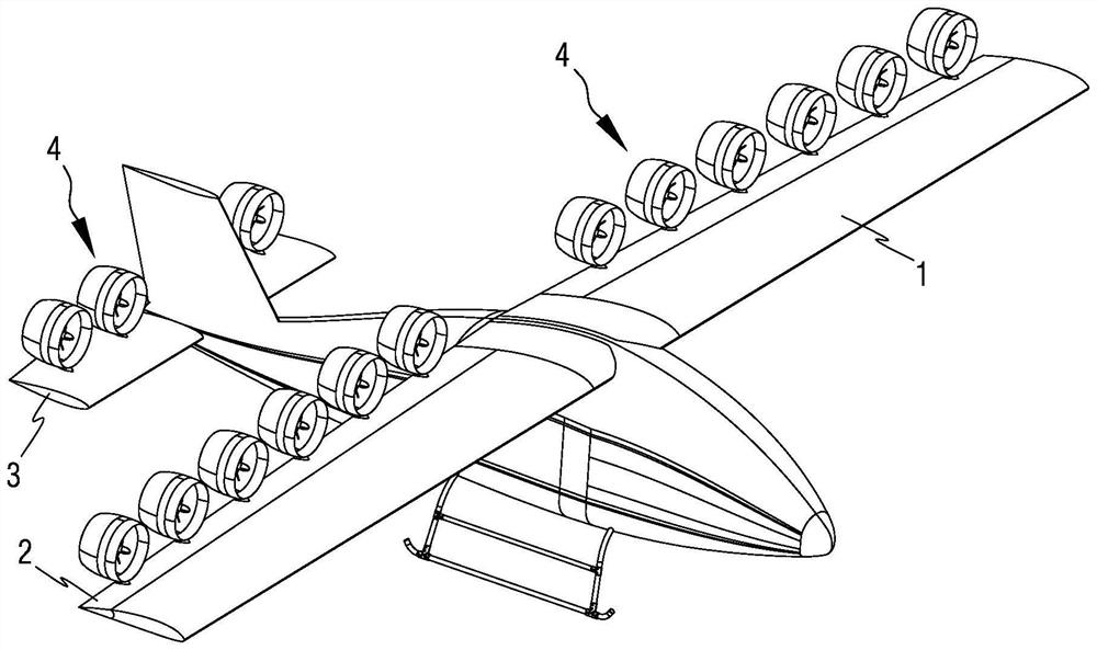
[0021] In the present invention, the electric propulsion engine 4 is installed on the integral flaperon and the full-motion horizontal tail, and the integral flaperon and the full-motion horizontal tail itself can deflect the direction, and the conventional design itself has a driving integral flap The structure of aileron and full-moving horizontal tail deflection, these are inherent functional structures of the aircraft, and are not dead weight structures. The invention utilizes the conventional structure of the aircraft to drive the electric propulsion engine to switch between the level flight state and the vertical take-off and landing state, does not need to set up an additional deflection mechanism, has no dead weight at all, reduces the energy consumption of the aircraft, and is beneficial to improve the aircraft range and Payload.

[0022] It should be noted that before the current electric propulsion technology matures, the structure of the movable surface such as the...


PUM


Abstract

The invention discloses an engine hanger for a tilting ducted aircraft, which is used for fixedly mounting an electric propulsion engine on the upper wing surfaces of an integral flaperon and a full-motion horizontal tail of the tilting ducted aircraft through the engine hanger. The electric propulsion engine can be driven to tilt between horizontal propulsion and vertical propulsion along with the deflection of the integral flaperon and the full-motion horizontal tail; the chordwise installation position of the engine hanging frame on the tilting movable face is determined by an intersection point A of the front edge of the engine hanging frame and the upper surface of the tilting movable face, and when the chord length of the tilting movable face is c, the chordwise position of the projection of the point A on the upper surface of the tilting movable face ranges from 0.42 c to 0.52 c. Through the optimized design of the hanging frame, structures such as the section shape of the hanging frame, the height of the supporting mechanism and the shapes of the front edge and the rear edge can be optimally designed according to the given engine duct, the wing surface efficiency and the safety of the rotor duct can be effectively improved, and the flutter characteristic is improved.

Description

technical field [0001] The invention relates to a support structure in the technical field of aircraft engines, in particular to a support structure for a tilting duct of an electric aircraft engine, and in particular to an engine pylon for a tilting duct aircraft. Background technique [0002] Aircraft engines usually use pylons as the main connection and support components between the engine and the aircraft, and are widely used in aircraft design. The electric propulsion engine is small in size and light in weight, has advantages such as environmental protection, low noise, economy, simple structure and easy maintenance, and its pylon design has not received enough attention. The design of the engine pylon requires comprehensive consideration of aerodynamics and structural safety. Although an overly thin shape is beneficial to reduce drag and increase flight range, it is not good for the structural flutter and dynamic response of the aircraft. Studies have shown that inap...

Claims


Application Information

Patent Timeline
Patent Type & Authority Applications(China)
IPC IPC(8): B64C3/32B64D27/26B64D27/40
CPCB64C3/32B64D27/40
Inventor 宗宁朱磊黎华
Owner 宗宁
Learn More