Image composite debugging method and system for laser radar echo signal simulation device
An echo signal and lidar technology, applied in the optical field, can solve the problems of image space composite accuracy decline, non-axis, etc., to meet the requirements of imaging quality, improve composite accuracy, and improve the effect of simulation quality
- Summary
- Abstract
- Description
- Claims
- Application Information
AI Technical Summary
Problems solved by technology
Method used
Image
Examples
Embodiment 1
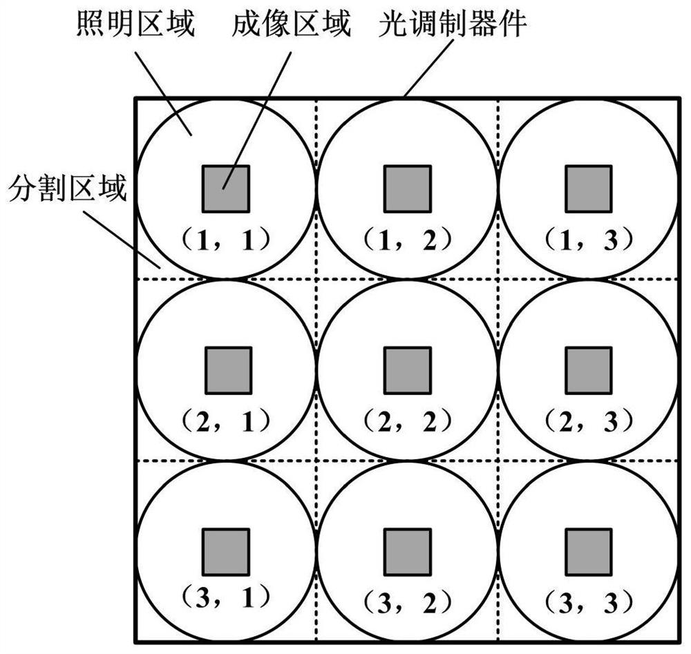
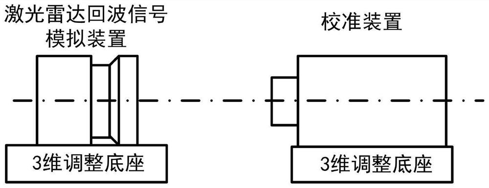
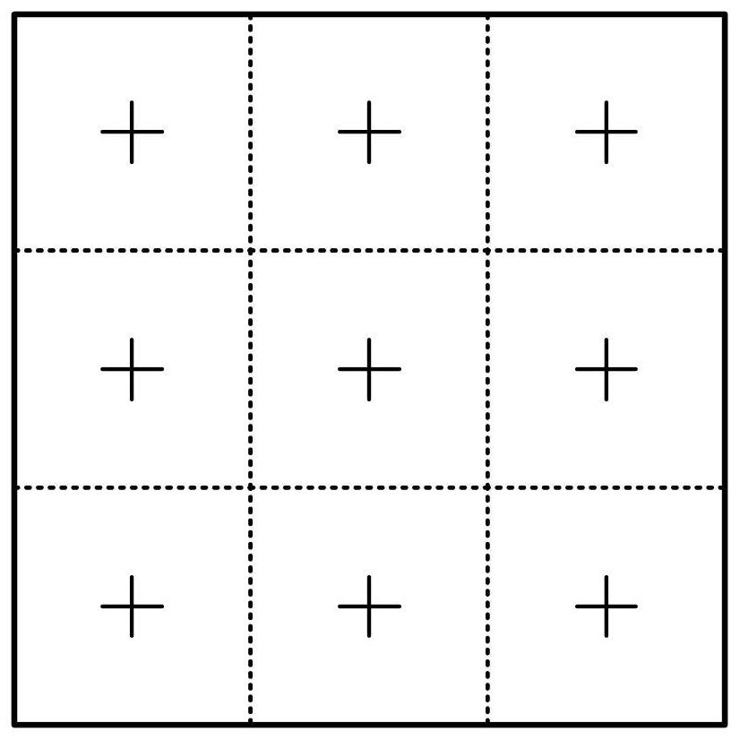
[0064] According to a method for image composite debugging of a laser radar echo signal simulation device provided by the present invention, such as Figure 1-Figure 9 shown, including:
[0065] Step S1: the light modulation device is divided into regions and numbered;
[0066] Step S2: setting the debugging and calibrating device according to the working band of the illuminating laser source;
[0067] Step S3: Debug the imaging position of the central segmented area and the imaging of the adjacent segmented area;
[0068] Step S4: Determine whether the four adjacent imaging areas meet the preset standard, and if they meet the preset standard, do not repeat the debugging; otherwise, repeat the debugging until all the areas meet the preset standard.
[0069] Specifically, it includes an image conversion module and an image composite module;
[0070] The image conversion module is a light modulation device divided into regions, and modulates the incident laser signal into an ...
Embodiment 2
[0086] Embodiment 2 is a preferred example of Embodiment 1, in order to describe the present invention in more detail.
[0087] Those skilled in the art can interpret the method for composite image debugging of a laser radar echo signal simulation device provided by the present invention as a specific implementation of an image composite debugging system for a laser radar echo signal simulation device, that is, the laser radar echo signal The system for compound debugging of images of a simulated device can be realized by executing the steps of the method for compound debugging of images of a simulated device of a laser radar echo signal.
[0088] An image composite debugging system for a laser radar echo signal simulation device provided according to the present invention includes:
[0089] Module M1: Divide and number the light modulation devices;
[0090] Module M2: Set the debugging and calibration device according to the working band of the illumination laser source;
...
Embodiment 3
[0110] Embodiment 3 is a preferred example of Embodiment 1, in order to describe the present invention in more detail.
[0111] The invention is mainly applied to a laser radar echo signal simulation system.
[0112] The technical problem to be solved by the present invention is to improve the composite precision of the slice image sequence, that is, to ensure that each imaging area of the optical modulation device divided by the area is coaxial with the corresponding microlens array through debugging, so that the position of each slice image sequence on the image plane is completely coincident . In order to solve the above problem, the present invention discloses a method for compound debugging of images of a laser radar echo signal simulation device.
[0113] The specific steps of this method are as follows:
[0114] 1. Light modulation device area division and numbering
[0115] The number of pixels of a single light modulation device is H×W, and it is equally divided ...
PUM
 Abstract
Description
Claims
Application Information
 - R&D
- Intellectual Property
- Life Sciences
- Materials
- Tech Scout
- Unparalleled Data Quality
- Higher Quality Content
- 60% Fewer Hallucinations
Browse by: Latest US Patents, China's latest patents, Technical Efficacy Thesaurus, Application Domain, Technology Topic, Popular Technical Reports.
© 2025 PatSnap. All rights reserved.Legal|Privacy policy|Modern Slavery Act Transparency Statement|Sitemap|About US| Contact US: help@patsnap.com


