Partition plate for plate mold and automatic partition plate adjusting device

An automatic adjustment and partition technology, applied in the direction of mold fixtures, mold auxiliary parts, manufacturing tools, etc., can solve the problems of raw material waste, large impact force of the partition, and high equipment input cost, so as to avoid low production efficiency and increase Installation stability, the effect of increasing the weighing capacity

Active Publication Date: 2022-06-24
JIANGSU TEEYER ENG MACHINERY
View PDF7 Cites 0 Cited by
  • Summary
  • Abstract
  • Description
  • Claims
  • Application Information

AI Technical Summary

Problems solved by technology

[0002] In the production process of aerated panels and aerated concrete blocks, molds are needed to inject raw materials into the molds and then transported to subsequent processes for processing. The length of the molds is 6 meters, and the length of conventional aerated panels It is 6 meters, and the individual length of the aerated concrete block will vary according to the demand. The conventional length is 1200 and 600 mm, but according to some needs, different lengths and sizes will be processed. If it is a block with a length of 600 mm , then the length of the mold can be fully compatible with the synchronous processing of aerated panels and aerated concrete blocks. The length of the block cannot be divisible by 6000 mm, then there will be excess raw materials that will be cut off at the end, resulting in waste of raw materials, and the material used to produce blocks is not the same as that of plates,

Method used


Image

  • Partition plate for plate mold and automatic partition plate adjusting device
  • Partition plate for plate mold and automatic partition plate adjusting device
  • Partition plate for plate mold and automatic partition plate adjusting device

Examples


Example Embodiment

[0073] The specific embodiments of the present invention will be described in further detail below with reference to the accompanying drawings and embodiments. The following examples are intended to illustrate the present invention, but not to limit the scope of the present invention.

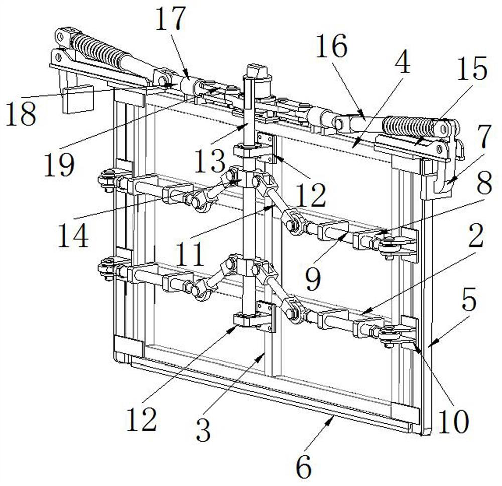
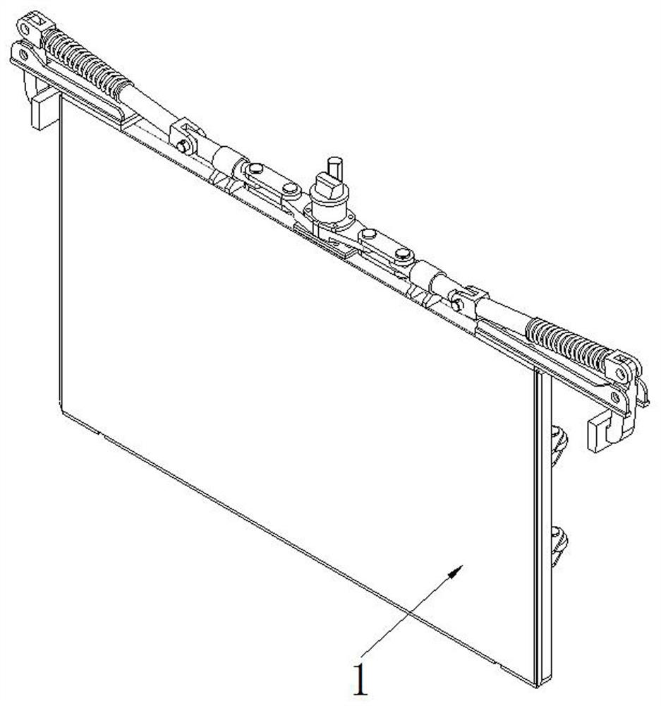
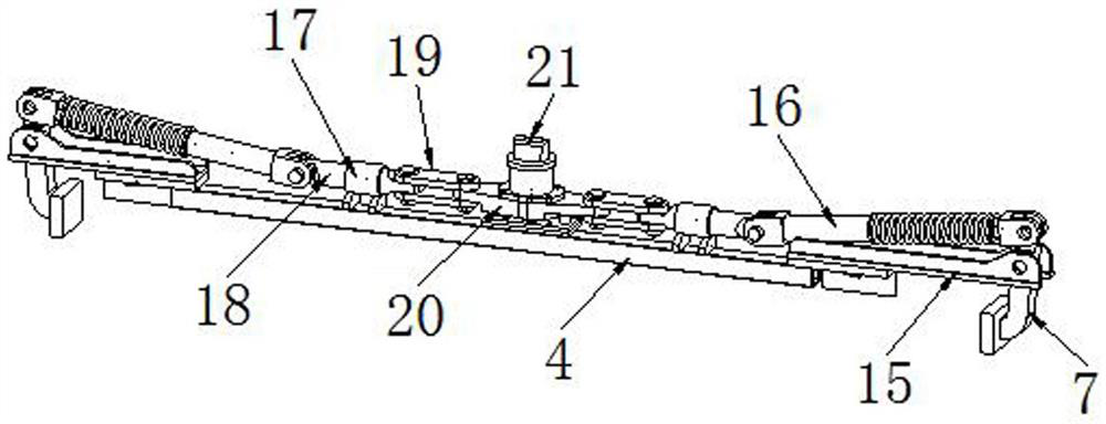
[0074] see figure 1 and figure 2 , one side of the baffle 1 is flat, such as figure 2 As shown, turn the plane side toward the side that needs to be filled with materials, and press the partition plate into the mold 32. At this time, a downward pressure is continuously provided on the upper part of the partition plate to ensure that the bottom plate 6 and the mold 32 are in contact with each other. The bottom is in direct and close contact, and then the side plate 5 is pushed outward by the side plate ejection mechanism, so that the surface of the side plate 5 is in contact with the inner wall of the mold 32. In the preliminary installation of the partition plate, the locking claw 7 is con...


PUM


Abstract

The invention relates to the technical field of plate building block production and processing, in particular to a partition plate for a plate mold and an automatic partition plate adjusting device. A plurality of parallel cross beams are welded to the other face of the baffle, a vertical beam is welded to the center of each cross beam, side plate ejection mechanisms are installed on the cross beams and the vertical beams, a cross supporting beam is arranged on the upper portion of the baffle, a top locking mechanism is arranged on the upper portion of the cross supporting beam, and a bottom plate flatly attached to the bottom of a mold is arranged below the baffle. The side plate ejection mechanism comprises side plates which are ejected outwards in parallel, and the top locking mechanism comprises locking claws exceeding the two ends of the baffle. The mold is divided into an empty groove section and a material injection section by the partition plate, the overall length of a product is adjusted by adjusting the position of the partition plate, the production requirements of plates and building blocks of different sizes are met, the material injection amount is effectively reduced by adjusting the size of the material injection section of the mold, raw materials are saved, and the production efficiency is improved. The purposes of energy conservation and emission reduction are achieved, and economic benefits are improved.

Description

technical field [0001] The invention relates to the technical field of plate block production and processing, and relates to a partition plate for a plate mold and an automatic adjustment device for the partition plate. Background technique [0002] In the production process of aerated boards and aerated concrete blocks, molds are needed to inject raw materials into the molds and then transport them to subsequent processes for processing. The length of the molds is 6 meters, and the length of conventional aerated boards is 6 meters. It is 6 meters, and the individual length of the aerated concrete block will vary according to the needs. The conventional length is 1200 and 600 mm, but according to some needs, different lengths will be processed. If it is a block with a length of 600 mm , then the length of the mold can be fully compatible with the simultaneous processing of the aerated board and the aerated concrete block. After processing, the corresponding length of the aer...

Claims


Application Information

Patent Timeline
IPC IPC(8): B28B1/50B28B7/00
CPCB28B1/50B28B7/0002B28B7/002Y02W30/91
Inventor 薛成张建军谢沛文吴敏王锋
Owner JIANGSU TEEYER ENG MACHINERY
Why Eureka
Try Eureka