Material belt and film separation equipment of chip mounter feeder and application of material belt and film separation equipment

A technology of feeder and placement machine, which is applied to the unsealing, packaging, cutting and unsealing of objects, etc. It can solve the problems of wasting more electronic components, occupying a large area, and extending the leader film when the tape is separated, so as to ensure communication Real-time, low cost, and the effect of avoiding electromagnetic interference

Pending Publication Date: 2022-06-24
河北擎展智能科技有限公司
View PDF0 Cites 0 Cited by
  • Summary
  • Abstract
  • Description
  • Claims
  • Application Information

AI Technical Summary

Problems solved by technology

In use, when multiple electronic components need to be attached, multiple feeders and multiple braids are required to be used side by side. The existing feeders are wider, occupy a larger area, and have more leads, which are very difficult to use. Confused, after the braid is conveyed, because the braid film needs a certain distance to be connected to the recovery mechanism of the material tape film, the separation of the front end of the braid wastes more electronic components, or requires additional extension of the tape film, and during the separation process The braiding can’t go backwards, it can only go forward, and the braiding needs to be long braiding or whole reel. When the braiding is short or non-full reel, it can’t be used, which causes great waste

Method used


Image

  • Material belt and film separation equipment of chip mounter feeder and application of material belt and film separation equipment
  • Material belt and film separation equipment of chip mounter feeder and application of material belt and film separation equipment
  • Material belt and film separation equipment of chip mounter feeder and application of material belt and film separation equipment

Examples


Embodiment

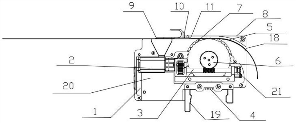
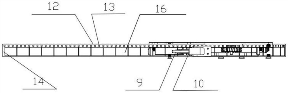
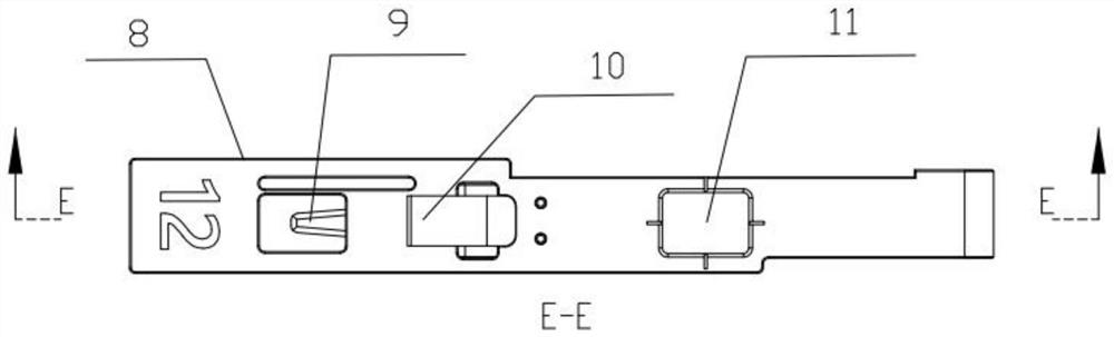
[0036] like figure 1 , Figure 8As shown, when in use, when the length of the braid is greater than 10cm, the braid 12 enters the guide rail 5 from the feeding port 17, starts the power mechanism 2, the driving tooth 7 on the driving wheel 6 and the braid on the braid 12. The hole 13 is engaged, the power mechanism 2 drives the drive wheel 6 to rotate through the transmission shaft, and at the same time, the drive tooth 7 drives the braid hole 13 to move forward, thereby driving the braid 12 to move into the guide rail 5, through the film pressing plate 15 and the cutting tool. Under the action of 9, the material film 16 is cut, and the cut fully enclosed film 16 is guided by the material tape film return guide 10, so that the braid 12 exposes the electronic components; Suck it away and stick it on the PCB. At this time, the fully enclosed film 16 is turned backward along the tape film return guide 10, and the braid 12 is discharged out of the feeder through the discharge po...


PUM


Abstract

The invention provides a material belt and film separation device of a chip mounter feeder and application of the material belt and film separation device, a braid is provided with a braid hole and an electronic element cavity, an electronic element is placed in the electronic element cavity, the electronic element cavity is provided with a fully-closed covering film, the material belt and film separation device comprises a shell, and an upper shell is arranged at the upper end of the shell; the upper shell is provided with a guide rail, a feeding port, a discharging port and a cutting tool, the upper end of the upper shell is provided with a material belt film turn-back guide plate, the rear end of the material belt film turn-back guide plate is provided with a material taking port, the material taking port is a through hole and is communicated with the guide rail, the upper shell is provided with a material film pressing plate, and the material film pressing plate is located at the upper end of the cutting tool; installation can be completed without a leading tape. The material changing time is shortened, the material belt can be replaced in only three seconds, and convenience and rapidness are achieved; a film drawing mechanism is omitted in the belt cutting mode, so that the feeder becomes the smallest feeder of the chip mounter in the world, and the feeder is small, exquisite, clean, low in cost and low in failure rate.

Description

technical field [0001] The invention relates to the field of feeding equipment applied to SMT placement machine equipment in PCB production, in particular to a material tape film separation device of a placement machine feeder and its application. Background technique [0002] The traditional feeder uses two independent mechanisms, which are the transmission mechanism of the material belt and the recovery mechanism of the material belt film, such as the full range of Siemens, the full range of YAMAHA, and the full range of Panasonic. The existing braid is provided with a braided hole and an electronic component cavity. The electronic component cavity has a braided film, and electronic components are placed in the electronic component cavity. The braided film is a plastic film with a thickness of 0.1mm. It is mainly used for Cover the electronic components so that they are encapsulated inside the tape. The braided film is hot-pressed or glued in the cavity of the electronic ...

Claims


Application Information

Patent Timeline
Patent Type & Authority Applications(China)
IPC IPC(8): B65B69/00
CPCB65B69/0033
Inventor 李波
Owner 河北擎展智能科技有限公司
Why Eureka
Try Eureka