
Conveying equipment for pressing steel ingots into steel plates and using method of conveying equipment

A technology for transmission equipment and steel plates, which is applied in the direction of conveyors, conveyor objects, transportation and packaging, etc. It can solve the problems of inconvenient removal of steel plates and lower work efficiency, so as to achieve convenient movement, improve practical performance, and reduce space occupation. Effect

Pending Publication Date: 2022-06-24
江苏瑞格高合金材料有限公司
View PDF0 Cites 0 Cited by
  • Summary
  • Abstract
  • Description
  • Claims
  • Application Information

AI Technical Summary

Problems solved by technology

[0002] When the steel plate is manufactured, it needs to go through a variety of processing steps, so it needs to be transported by an assembly line when it is processed, and then it is manually picked up for some steps that cannot be processed by machinery. The steel plate is placed on the track for transmission. Since the steel plate is in the shape of a thin plate, it is inconvenient to manually remove the steel plate attached to the track, thereby reducing its work efficiency.

Method used


Image

  • Conveying equipment for pressing steel ingots into steel plates and using method of conveying equipment
  • Conveying equipment for pressing steel ingots into steel plates and using method of conveying equipment
  • Conveying equipment for pressing steel ingots into steel plates and using method of conveying equipment

Examples


Embodiment Construction

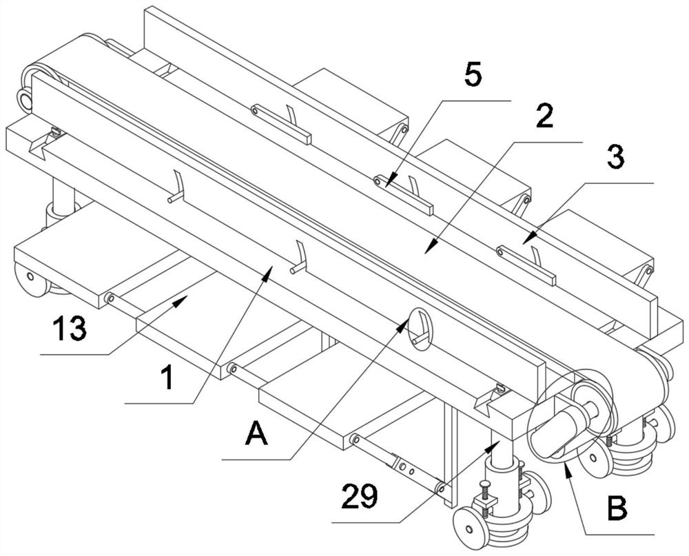
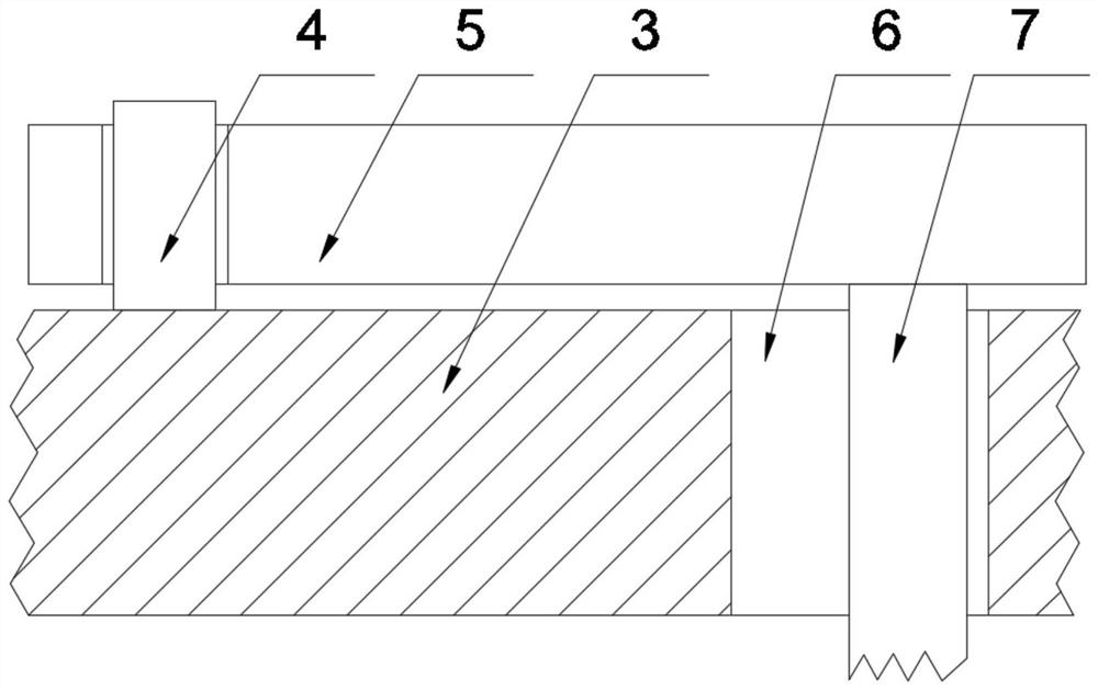
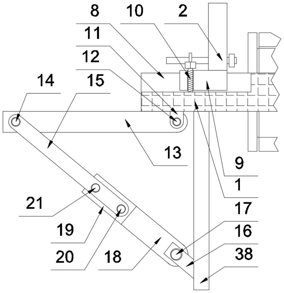
[0028] The technical solutions in the embodiments of the present invention will be clearly and completely described below with reference to the accompanying drawings in the embodiments of the present invention. Obviously, the described embodiments are only a part of the embodiments of the present invention, but not all of the embodiments. Based on the embodiments of the present invention, all other embodiments obtained by those of ordinary skill in the art without creative efforts shall fall within the protection scope of the present invention.

[0029] The present invention provides such as Figure 1-6 The shown transmission equipment for pressing a steel ingot into a steel plate and a method of using the same include a carrying platform 1, and a crawler belt 2 is arranged on the carrying platform 1. Under the action, the steel plate follows the crawler 2 to maintain relative movement, so that the crawler 2 transmits the steel plate with a certain height under the action of t...


PUM


Abstract

The conveying equipment comprises a bearing table, a crawler belt is arranged on the bearing table, limiting plates are arranged on the two sides of the top of the bearing table, a plurality of first pin shafts are fixedly connected to the bottoms of the opposite sides of the two limiting plates at equal intervals, and the outer walls of the first pin shafts are rotationally and alternately sleeved with flow guide plates; a plurality of sliding holes are formed in one side of the limiting plate at equal intervals, a handle is fixedly connected to one side of the flow guide plate, the outer wall of the handle is slidably connected with inner cavities of the sliding holes in a sleeved mode, a driving device is arranged on one side of the bearing table, and supporting devices are arranged at the four corners of the bottom of the bearing table. According to the steel plate conveying device, the arrangement mode that the crawler belt, the limiting plates and the flow guide plate are matched is utilized, when a steel plate is conveyed on the crawler belt, the two limiting plates can limit the position of the steel plate, the flow guide plate can rotate by lifting a handle, and therefore the steel plate conveyed on the crawler belt is jacked up, the steel plate can be conveniently and manually taken, and the working efficiency of the steel plate conveying device is improved.

Description

technical field [0001] The invention relates to the field of production lines, in particular to a conveying device for pressing a steel ingot into a steel plate and a method for using the same. Background technique [0002] When the steel plate is manufactured, it needs to go through a variety of processing steps, so it needs to be transported by an assembly line when it is processed, and then it is manually picked up to perform some steps that cannot be processed by machinery. The steel plate is placed on the track to transmit it. Since the steel plate is in the shape of a thin plate, it is inconvenient to manually remove the steel plate attached to the track, thereby reducing its work efficiency. SUMMARY OF THE INVENTION [0003] The purpose of the present invention is to provide a conveying device for pressing a steel ingot into a steel plate and a method of using the same, so as to solve the problems raised in the above-mentioned background art. [0004] In order to a...

Claims


Application Information

Patent Timeline
IPC IPC(8): B65G21/20B65G41/00B65G47/22
CPCB65G21/2072B65G41/008B65G47/22
Inventor 武星华王瑞峰周龙善简光明刘明
Owner 江苏瑞格高合金材料有限公司
Learn More