
Gear reducer base with vibration reduction function

A gear reduction and base technology, applied in gear lubrication/cooling, belt/chain/gear, mechanical equipment, etc., can solve the problem of gear reducer lubricating oil leakage, gear reducer lubricating oil solidification, and gear reducer operation difficulties And other problems, to avoid the effect of high or low temperature

Pending Publication Date: 2022-06-24
杨多
View PDF0 Cites 0 Cited by
  • Summary
  • Abstract
  • Description
  • Claims
  • Application Information

AI Technical Summary

Problems solved by technology

[0003] When the gear reducer is running, due to the gap between the two gears, the pitch circles of the gears contact each other and generate vibration. In order to avoid damage to the gear reducer caused by vibration, people have manufactured a gear reducer with vibration reduction function. base to solve this problem. At the same time, the working environment temperature of the existing gear reducer is plus or minus 40 degrees. When the working environment temperature of the gear reducer is too high, the lubricating oil inside the gear reducer will leak out, affecting The stability of the operation of the gear reducer. When the working environment temperature of the gear reducer is too low, the lubricating oil inside the gear reducer will solidify, which will make the operation of the gear reducer difficult. However, there is no solution to this problem on the market. Gear reducer base

Method used


Image

  • Gear reducer base with vibration reduction function
  • Gear reducer base with vibration reduction function
  • Gear reducer base with vibration reduction function

Examples


Embodiment Construction

[0023] The technical solutions in the embodiments of the present invention will be clearly and completely described below with reference to the accompanying drawings in the embodiments of the present invention. Obviously, the described embodiments are only a part of the embodiments of the present invention, rather than all the embodiments. Based on the embodiments of the present invention, all other embodiments obtained by those of ordinary skill in the art without creative efforts shall fall within the protection scope of the present invention.

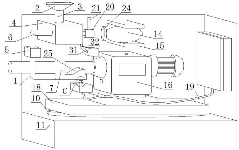
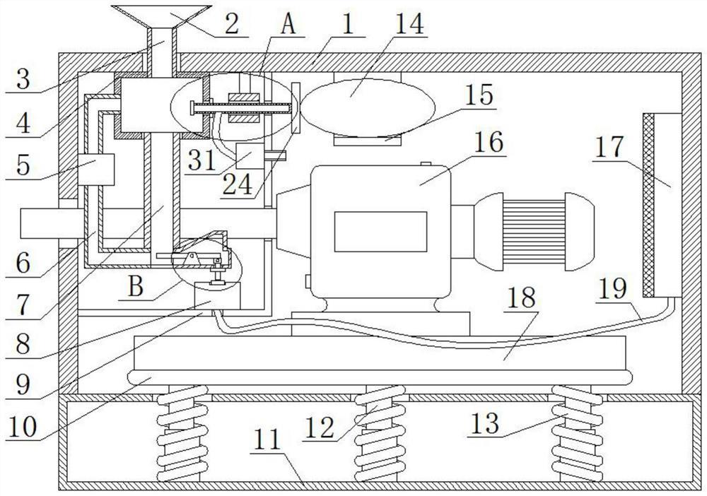
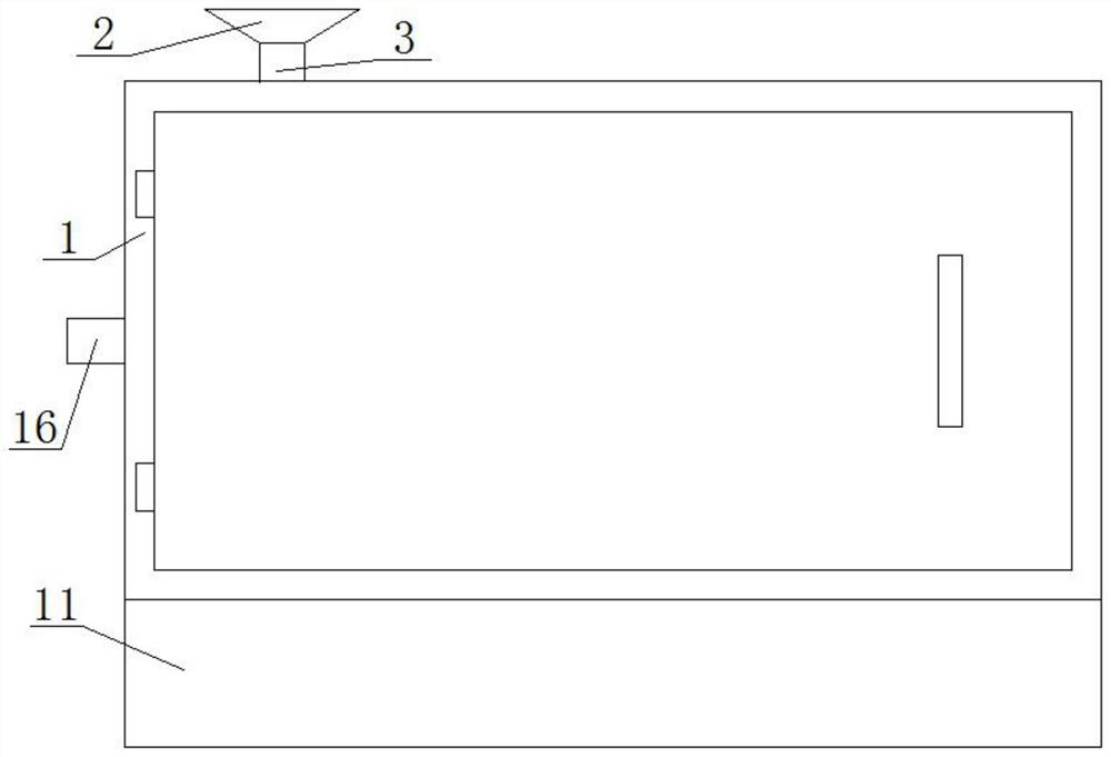
[0024] see Figure 1-8 , the present invention provides a technical solution: a gear reducer base with a vibration reduction function, comprising a horizontally arranged box body 1, the front side of the box body 1 is provided with a second opening, and the front side of the second opening There is a movable door, and hinges are fixedly connected to the left side of the movable door near the upper and lower sides. The movable door is...


PUM


Abstract

The gear reducer base with the vibration reduction function comprises a horizontally-arranged box body, a first opening is formed in the bottom of the box body, a base is fixedly connected to the bottom of the box body, three telescopic rods are fixedly connected to the bottom of an inner cavity of the base, and the three telescopic rods are sequentially and linearly arranged from left to right; the top ends of the three telescopic rods all penetrate through the top of the inner cavity of the base, and the top ends of the three telescopic rods all penetrate through the first opening and extend to the inner cavity of the box body; through mutual cooperation of the water storage tank, the transverse pipe, the water pumping pipe, the water pump, a water outlet pipe, a feeding pipe, a feeding hopper, a box body, a fixed block, a movable plate, a connecting block, a movable rod, a power starter, a cable, a heating plate and other structures, the temperature of an inner cavity of the box body can be controlled, and the working environment of the gear reducer is kept at a certain temperature; and the condition that the temperature is too high or too low is avoided.

Description

technical field [0001] The invention relates to the technical field of household products, in particular to a gear reducer base with a vibration reduction function. Background technique [0002] The gear reducer is an independent closed transmission device between the prime mover and the working machine. It is used to reduce the speed and increase the torque. It is widely used in metallurgy, mining, lifting, transportation, cement, construction, chemical industry, textile, printing and dyeing. , pharmaceutical and other fields. [0003] When the gear reducer is running, due to the gap between the two gears, the pitch circles of the gears contact each other and vibrate. In order to avoid damage to the gear reducer caused by vibration, a gear reducer with vibration reduction function has been created. At the same time, the working environment temperature of the existing gear reducer is plus or minus 40 degrees. When the working environment temperature of the gear reducer is t...

Claims


Application Information

Patent Timeline
IPC IPC(8): F16H57/04F16H57/028F16H57/025
CPCF16H57/0412F16H57/028F16H57/025
Inventor 杨多
Owner 杨多
Learn More