
Flash memory test method, programmable logic device, storage medium and system

A flash memory storage and testing method technology, applied in static memory, instruments, biological neural network models, etc., can solve the problem of lack of error bit rate, raw bit error rate and mean time between failures and other automated testing technologies

Active Publication Date: 2022-06-24
上海威固信息技术股份有限公司
View PDF4 Cites 0 Cited by
  • Summary
  • Abstract
  • Description
  • Claims
  • Application Information

AI Technical Summary

Problems solved by technology

[0004] The present invention provides a flash memory testing method, a programmable logic device, a storage medium and a system, which can solve the lack of unrepairable error bit rate for flash memory in the prior art, The problem of automated testing technology of raw bit error rate and mean time between failures, to achieve the purpose of statistics of flash memory reliability data in actual complex tests

Method used


Image

  • Flash memory test method, programmable logic device, storage medium and system
  • Flash memory test method, programmable logic device, storage medium and system
  • Flash memory test method, programmable logic device, storage medium and system

Examples


Embodiment 1

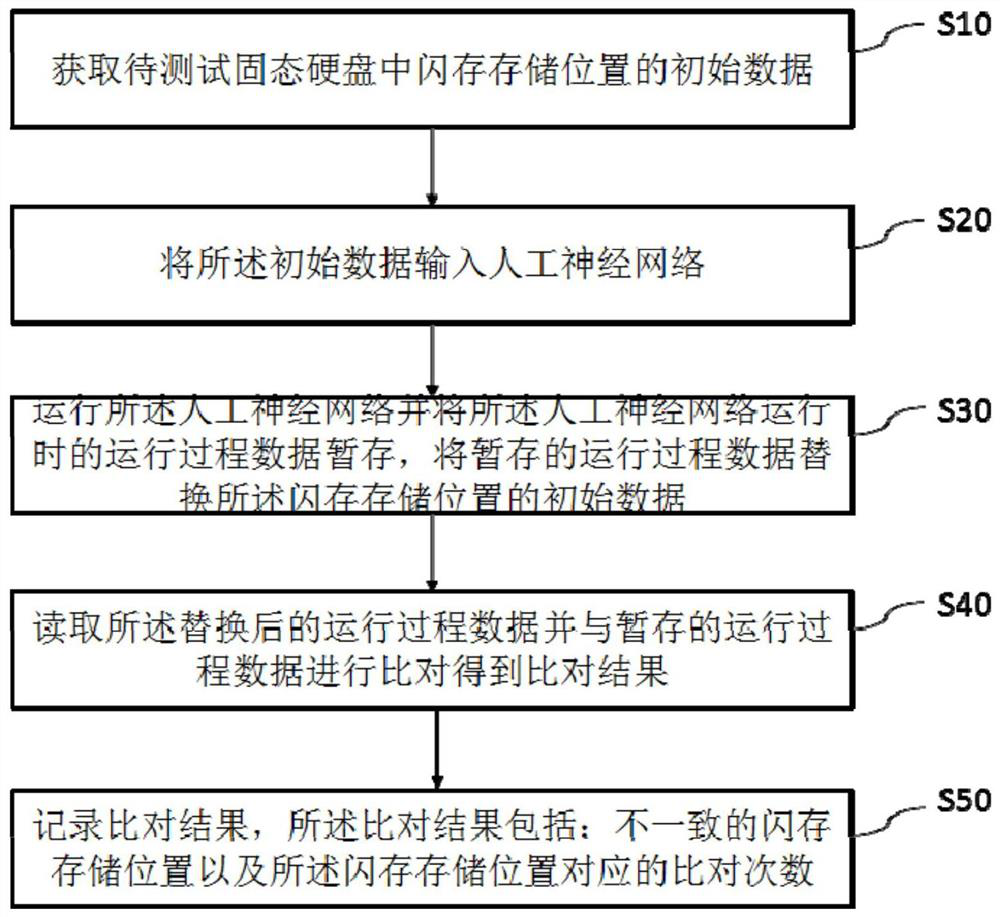
[0034] This embodiment provides a flash memory testing method, such as figure 1 shown, including the following steps:

[0035] S10. Obtain initial data of the flash memory storage location in the solid-state drive to be tested;

[0036] S20, inputting the initial data into an artificial neural network;

[0037] S30, running the artificial neural network and temporarily storing the running process data when the artificial neural network is running, and replacing the initial data of the flash memory storage location with the temporarily stored running process data;

[0038] S40, read the operating process data after the replacement and compare with the temporarily stored operating process data to obtain a comparison result;

[0039] S50. Record a comparison result, where the comparison result includes: inconsistent flash memory storage locations and the number of comparisons corresponding to the flash memory storage locations.

[0040] In this embodiment, if the comparison re...

Embodiment 2

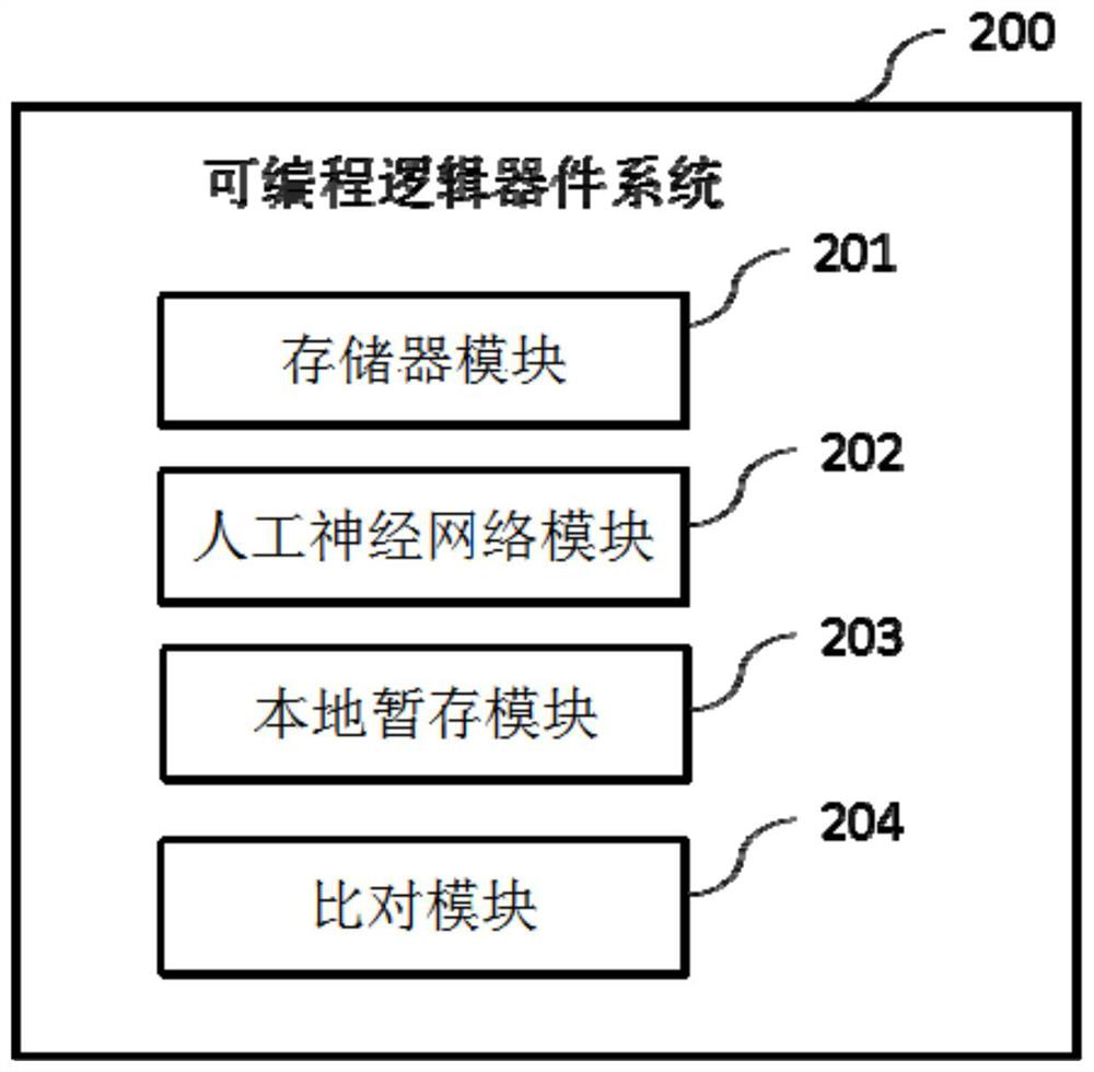
[0046] This embodiment provides a programmable logic device 2 that is configured to implement the flash memory testing method in Embodiment 1.

[0047] In this embodiment, as figure 2 As shown, the programmable logic device is connected to the bridge module 1, and the programmable logic device 2 is configured to include:

[0048] The FIFO module 201 is used to receive the read-write data converted by the bridge module 1, and output the read-write data according to the first-in, first-out mode;

[0049] The artificial neural network module 202 is used to connect multiple FIFO modules 201, input the output data of the FIFO module 201 into the artificial neural network module 202 and run the artificial neural network, and then pass the operation process data of the artificial neural network through the FIFO module. 201 and the bridging module 1 replace the data of the flash memory storage location in the solid-state disk to be tested, read the replaced data of the flash memory ...


PUM


Abstract

The invention discloses a flash memory testing method, a programmable logic device, a storage medium and a system. The method comprises the following steps: acquiring initial data of a flash memory storage position in a solid state disk to be tested; inputting the initial data into an artificial neural network; running the artificial neural network and refreshing the data at the storage position of the flash memory; comparing the refreshing data with the running process data; and recording the flash memory storage positions with inconsistent data comparison and the comparison times of the flash memory storage positions. According to the invention, the reliability test of the storage position of the flash memory can be realized, and the irreparable error bit rate, the original bit error rate and the average fault interval time are calculated and determined according to the storage position of the flash memory which is recorded inconsistently and the comparison times of the storage position of the flash memory.

Description

technical field [0001] The invention relates to the field of memory testing, in particular to a flash memory testing method, a programmable logic device, a storage medium and a system. Background technique [0002] The reliability of memory is closely related to the stability of system operation and data security, especially for enterprise-level memory. As flash memory is the main component of solid-state drives, reliability is also critical and needs to be evaluated before application. When the memory cells of flash memory are working, the memory cells will naturally undergo bit flips over time due to temperature changes and process variations. Error correction codes can be used to correct the abnormally flipped bits, but they cannot be identified and corrected. All errors. [0003] The testing of flash memory in the prior art includes testing methods such as engineering verification testing, design verification testing, reliability testing, and high-temperature testing. ...

Claims


Application Information

Patent Timeline
IPC IPC(8): G11C29/56G06N3/04
CPCG11C29/56G06N3/04
Inventor 吴佳李礼吴叶楠
Owner 上海威固信息技术股份有限公司
Learn More