Supercharge Your Innovation With Domain-Expert AI Agents!

Overcurrent monitoring device

A monitoring device and overcurrent technology, which is applied in the direction of machines/supports, casings/cabinets/drawer parts, supporting machines, etc. It can solve the problems of inability to adjust the height of different groups of people, inconvenient position movement, and inability to fix transformers, etc. , to achieve the effect of enhancing the adaptability and clamping firmness and less force

Pending Publication Date: 2022-06-28
广东电力通信科技有限公司
View PDF22 Cites 0 Cited by
  • Summary
  • Abstract
  • Description
  • Claims
  • Application Information

AI Technical Summary

Problems solved by technology

[0002] With the extensive construction of smart grids and power systems in the fields of the Internet of Things and digital grids, a large number of microelectronic devices have been applied in secondary systems. The probability of electronic equipment being damaged by electromagnetic pulse, transient overvoltage, transient overcurrent, and stray voltage is gradually increasing. Transient overvoltage means that when the power system is operating normally, the insulation of electrical equipment is under the rated voltage of the power supply. , operation, fault or parameter configuration and other reasons make the voltage of a certain part of the system rise greatly beyond the value of normal operation, and the transient overcurrent signal of the transformer also needs to be monitored. At present, the transient overcurrent signal monitoring device of the transformer is widely used. However, the existing transformer transient overcurrent signal monitoring device still has the problems of being unable to fix different transformers, resulting in unstable monitoring, unable to record monitoring data and not having monitoring and protection functions.
[0003] Most of the current overcurrent monitoring devices are fixed, which is inconvenient to move and cannot be adjusted according to the height of different groups of people. An overcurrent monitoring device is needed to solve this problem

Method used


Image

  • Overcurrent monitoring device
  • Overcurrent monitoring device
  • Overcurrent monitoring device

Examples


Embodiment 1

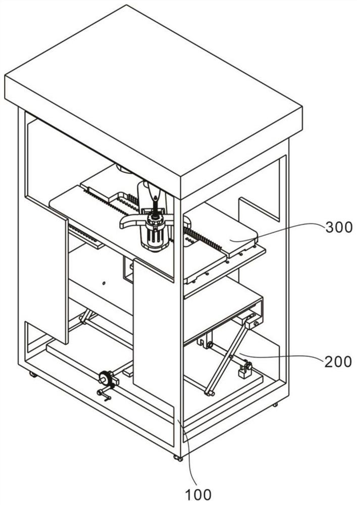
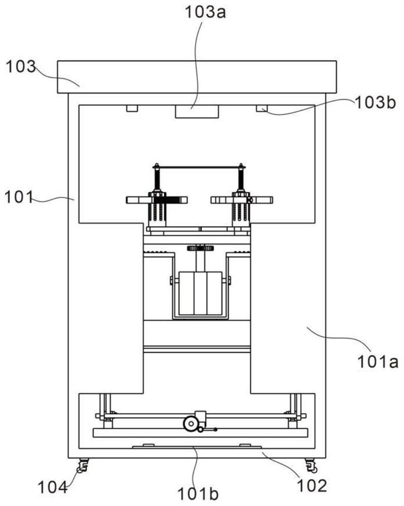
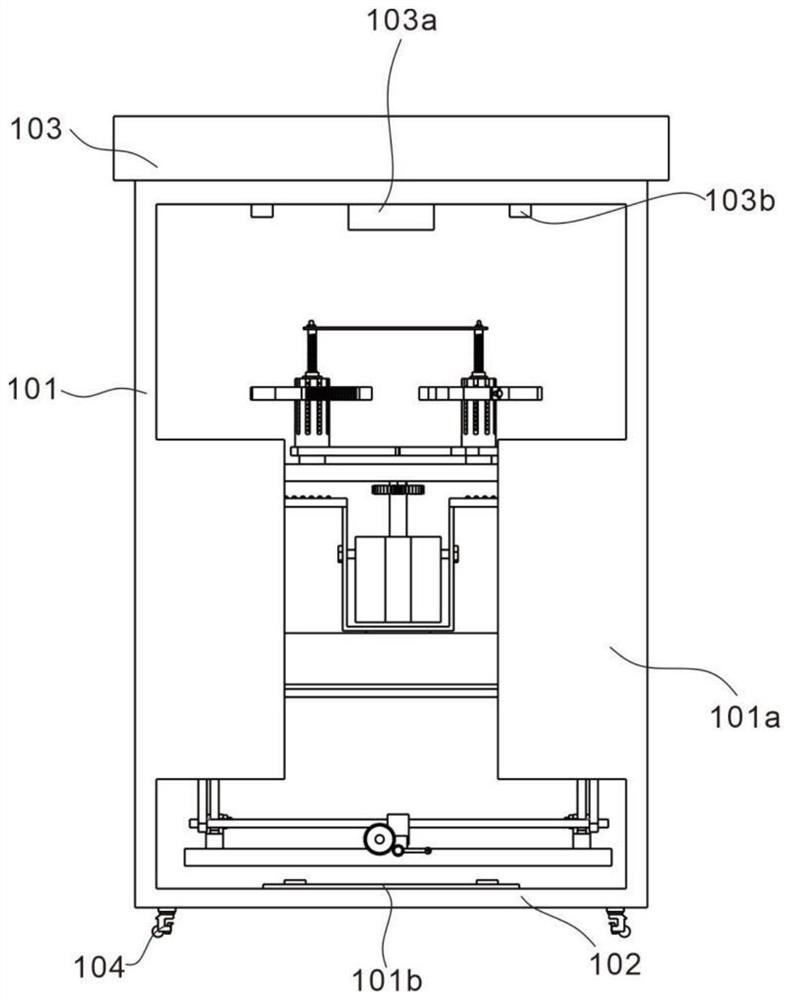
[0034] refer to Figure 1 to Figure 9 , is the first embodiment of the present invention. This embodiment provides an overcurrent monitoring device including a housing unit 100, the housing unit 100 includes a housing 101, a base 102, a top plate 103 and a moving wheel 104, the The casing 101 is disposed above the base 102, the top plate 103 is installed on the top of the casing 101, and the moving wheels 104 are fixed around the bottom of the base 102; and,

[0035] Lifting unit 200, the lifting unit 200 includes a hand crank 201, a cross movable frame 202, a support plate 203 and a bottom plate 204, the hand crank 201 is installed on the outer edge of the bottom plate 204, and the cross movable frame 202 is symmetrically installed on the between the support plate 203 and the bottom plate 204 , and the cross movable frame 202 is movably connected with the support plate 203 and the bottom plate 204 .

[0036] When in use, the housing 101 provides the protection and support fu...

Embodiment 2

[0038] refer to Figure 1 to Figure 9, which is the second embodiment of the present invention. Based on the previous embodiment, this embodiment provides an implementation of an overcurrent monitoring device, including a hollow structure design of the casing 101 and a baffle 101a on one side. A weighing scale 101b is also arranged inside the housing 101, two sliding bars 203a are arranged below the support plate 203, and a slider 203b is arranged above the sliding bars 203a, and the slider 203b can slide along the sliding bar 203a, Two fixing hooks 203c are symmetrically arranged below the support plate 203 , the fixing hooks 203c are movably connected with the cross movable frame 202 , and a positioning hole 203d is further arranged above the support plate 203 .

[0039] Further, the hand crank 201 further includes a primary gear 201a and a secondary gear 201b, the primary gear 201a and the hand crank 201 are fixedly connected by bolts, and the secondary gear 201b is fixed t...

Embodiment 3

[0042] refer to Figure 1 to Figure 9 , is the third embodiment of the present invention. Based on the previous two embodiments, this embodiment provides an implementation of an overcurrent monitoring device, and further includes a clamping unit 300, and the clamping unit 300 includes two sliding The plate 301 , the guard frame 302 and the limiting column 303 , the two sliding plates 301 are symmetrically arranged above the guard frame 302 , and the limiting column 303 is respectively arranged above the two sliding plates 301 .

[0043] Further, the clamping unit 300 further includes a clamping plate 304, a motor 305, a driving wheel 306 and a pressing plate 307, the clamping plate 304 is respectively disposed above the two sliding plates 301, and the motor 305 is disposed on the In the middle of the cage 302 , the driving wheel 306 is arranged at the end of the motor 305 , and the pressing plate 307 is arranged above the clamping plate 304 .

[0044] Preferably, several smal...


PUM


Abstract

The overcurrent monitoring device comprises a cleaning assembly, the cleaning assembly comprises a shell unit, the shell unit comprises a shell, a base, a top plate and moving wheels, the shell is arranged above the base, the top plate is installed at the top of the shell, and the moving wheels are fixed to the periphery of the lower portion of the base; the lifting unit comprises a hand crank, cross-shaped movable frames, a supporting plate and a bottom plate, the hand crank is installed on the outer side of the edge of the bottom plate, the cross-shaped movable frames are symmetrically installed between the supporting plate and the bottom plate, and the cross-shaped movable frames are movably connected with the supporting plate and the bottom plate and can be matched with various parts of different specifications; and in the lifting process and the clamping process, accurate lifting and firm clamping can be achieved, and the monitoring process of all parts is facilitated.

Description

technical field [0001] The invention relates to the technical field of overcurrent signal monitoring, in particular to an overcurrent monitoring device. Background technique [0002] With the widespread construction of smart grids and power systems in the field of Internet of Things and digital grids, a large number of microelectronic devices have been applied in secondary systems. The probability of electronic equipment being damaged by electromagnetic pulse, transient overvoltage, transient overcurrent and stray voltage gradually increases. , operation, fault or parameter configuration, etc., the voltage of a certain part of the system rises to a voltage that greatly exceeds the value of normal operation, and the transformer transient overcurrent signal also needs to be monitored. At present, the transformer transient overcurrent signal monitoring device is widely used. However, the existing transformer transient overcurrent signal monitoring device still has the problems...

Claims


Application Information

Patent Timeline
Patent Type & Authority Applications(China)
IPC IPC(8): F16M11/04F16M11/18F16M11/42H05K5/02
CPCF16M11/42F16M11/046F16M11/043F16M11/18H05K5/02
Inventor 杨志花罗崇立吴振田王敏刘炜伦王秀竹钟震宇李森林吕灵智龙邹韦荣桃廖颖茜尹震超
Owner 广东电力通信科技有限公司
Features
  • R&D
  • Intellectual Property
  • Life Sciences
  • Materials
  • Tech Scout
  • Unparalleled Data Quality
  • Higher Quality Content
  • 60% Fewer Hallucinations
Learn More