
Optical unit with shake correction function

An optical unit and jitter correction technology, applied in the directions of optics, electrical components, color TV components, etc., can solve problems such as increased load and movement obstruction of movable bodies, and achieve the effect of small configuration space

Active Publication Date: 2022-06-28
SANKYO SEIKI MFG CO LTD
View PDF6 Cites 0 Cited by
  • Summary
  • Abstract
  • Description
  • Claims
  • Application Information

AI Technical Summary

Problems solved by technology

At this time, the movement of the movable body is hindered by the elasticity of the flexible printed circuit board, and the load for swinging the movable body may increase.

Method used


Image

  • Optical unit with shake correction function
  • Optical unit with shake correction function
  • Optical unit with shake correction function

Examples


Embodiment Construction

[0044] Hereinafter, embodiments of the optical unit with a shake correction function to which the present invention is applied will be described with reference to the drawings.

[0045] (the whole frame)

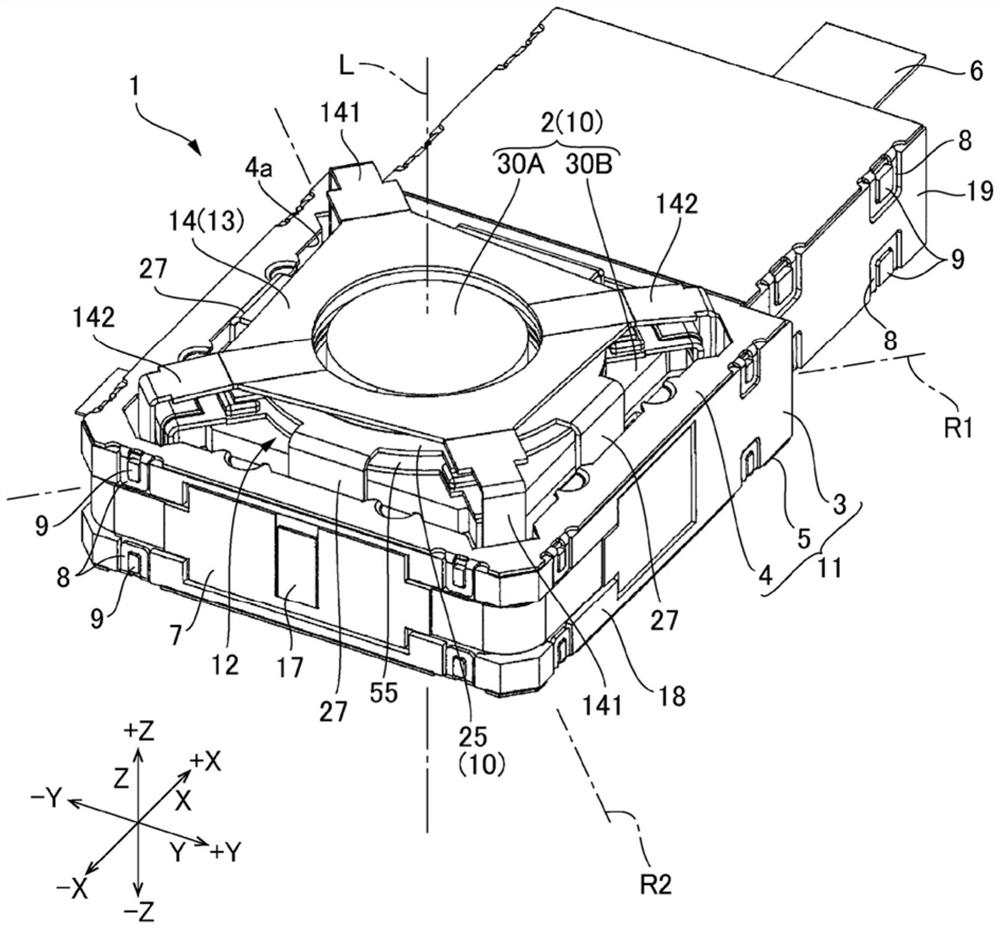
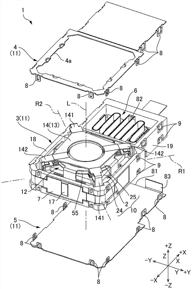
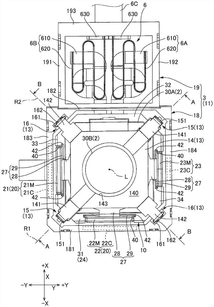
[0046] figure 1 It is a perspective view of the optical unit with shake correction function. figure 2 This is an exploded perspective view of the optical unit with shake correction function. image 3 This is a plan view of the optical unit with shake correction function with the cover removed from the subject side. Figure 4 This is an exploded perspective view of the optical unit with shake correction function with the cover and base removed.

[0047] like figure 1 As shown, the optical unit 1 with a shake correction function includes a movable body 10 including a camera module 2 and a fixed body 11 that surrounds the movable body 10 from the outside. The fixed body 11 includes a frame-shaped casing 3 that surrounds the movable body 10 from the outer peripheral side, ...


PUM


Abstract

The invention provides an optical unit with a shake correction function, which enables a movable body to rotate, reduces the spring constant of a flexible printed circuit board connected with the movable body, and reduces the configuration space of the flexible printed circuit board. An optical unit (1) with a shake correction function performs shake correction by rotating a movable body (10) around an optical axis L, an X axis, and a Y axis. A flexible printed circuit board (6) connected to a movable body is provided with a first branch portion (6A), a second branch portion (6B), and a lead-out portion (6C) connected to the ends of the first branch portion and the second branch portion in the + X direction. The first branch portion and the second branch portion are each provided with a planar portion (610) bent in a virtual plane (P) along the XY plane, and a meandering portion (620) bent from the planar portion in the optical axis L direction, meandering in the X-axis direction, and extending in the Y-axis direction. The flat portion (610) and the serpentine portion overlap when viewed from the optical axis L direction.

Description

technical field [0001] The present invention relates to an optical unit with a shake correction function which makes a camera module oscillate to correct the shake. Background technique [0002] Among the optical units installed in a portable terminal or a moving body, there is an optical unit having a camera module that swings or rotates a moving body provided with a camera module in order to suppress disturbance of a captured image when the portable terminal or the moving body moves. Mechanism that corrects jitter. Patent Document 1 describes such an optical unit with a shake correction function. [0003] The optical unit with a shake correction function of Patent Document 1 includes: a movable body including an optical module; a fixed body; ) rotating swing support mechanism. The flexible printed circuit board connected to the optical module is drawn out from the movable body. [0004] In the optical unit with a shake correction function, the movable body swings while...

Claims


Application Information

Patent Timeline
Patent Type & Authority Applications(China)
IPC IPC(8): H04N5/225G03B5/00H04N5/232G03B30/00
CPCG03B5/00G03B30/00G03B2205/0007H04N23/50H04N23/687
Inventor 笠原章吾
Owner SANKYO SEIKI MFG CO LTD
Learn More