
Film pressure sensor

A thin-film pressure and sensor technology, applied in the direction of instruments, measuring forces, measuring devices, etc., can solve the problems of small measurement range, inability to install, and cannot be applied to engineering applications, and achieve the effect of improving the reliability of measurement

Pending Publication Date: 2022-07-01
无锡尚合达智能科技有限公司
View PDF0 Cites 2 Cited by
  • Summary
  • Abstract
  • Description
  • Claims
  • Application Information

AI Technical Summary

Problems solved by technology

[0004]In the application field of vehicle weighing systems, due to factors such as small installation space, frequent vibration and shock, and large preload, the conventional weighing pressure sensors listed above product is not suitable for this specific engineering application
The size of the large-range pressure sensor is too large to be installed; the measurement range of the smaller-sized sensor is too small to meet the requirements of the load-carrying capacity required in the field of vehicle weighing applications
[0005]The deformation displacement sensor detects the micro-deformation or displacement of the frame or axle and converts it into weight through an algorithm. The disadvantage lies in the uncertainty of the material properties of the frame or axle. The collected micro-deformation or displacement is uncontrollable, with low precision and large error
[0006] At the same time, in the existing vehicle load cell solution, there are mostly problems with the performance of the vehicle load under extreme conditions, and it is impossible to avoid the damage to the sensor itself caused by the overall shear force caused by the vehicle overload, thus affecting the vehicle weighing accuracy, so for these problems, this application proposes a solution

Method used


Image

  • Film pressure sensor
  • Film pressure sensor
  • Film pressure sensor

Examples


Embodiment Construction

[0025] The present application will be further described below with reference to specific embodiments.

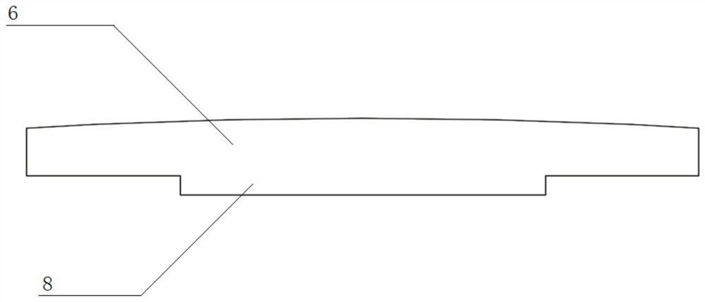
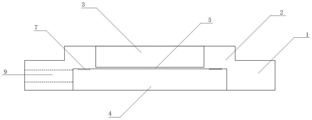
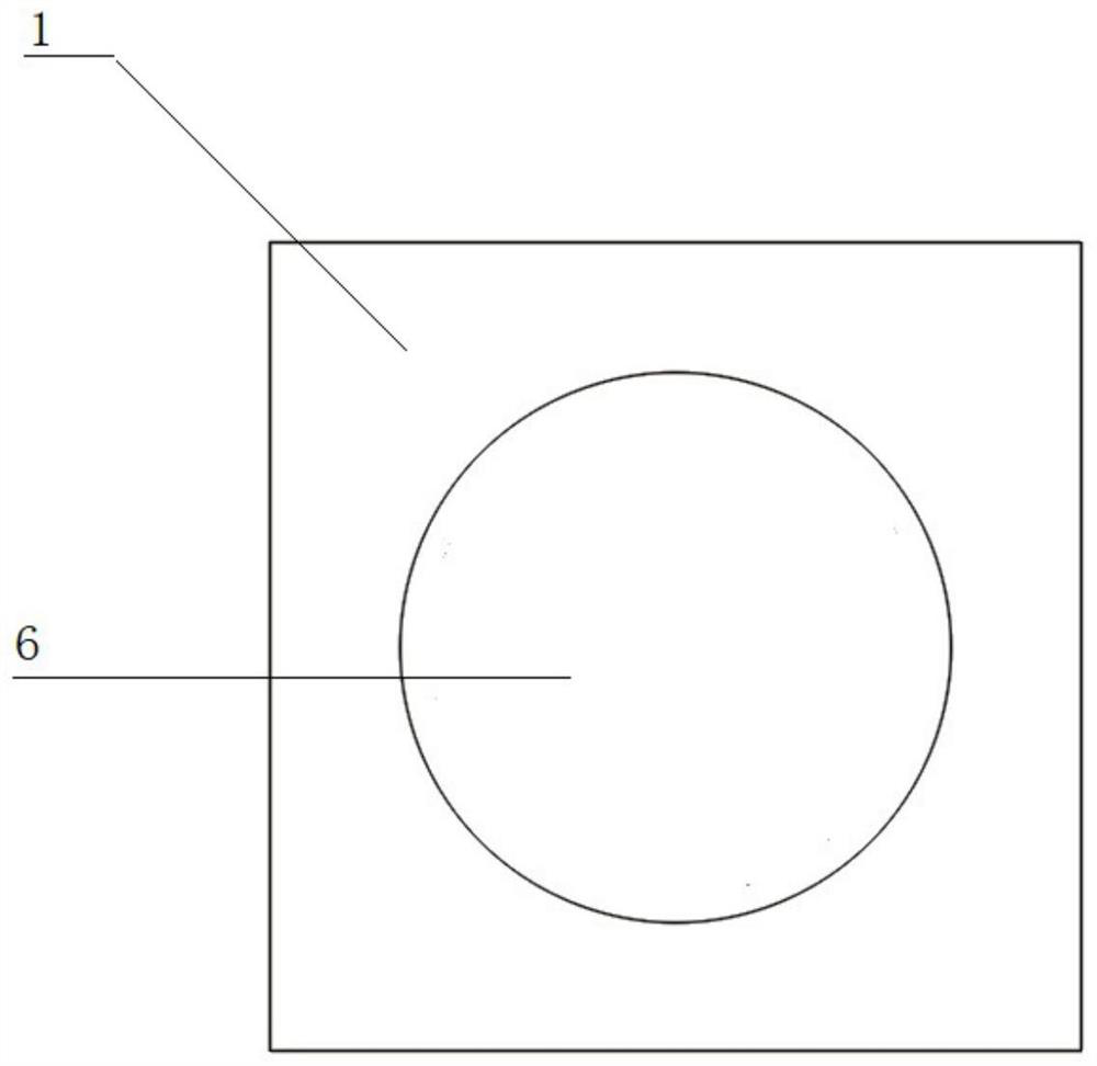
[0026] like Figure 1-3 As shown, it is a schematic diagram of the structure of the application. In this embodiment, the body 1 is a metal block, a cylindrical metal block protrusion 2 is provided in the center of the top of the body 1, and a cylindrical first metal block protrusion 2 is provided in the center of the cylindrical metal block protrusion 2. The cavity 3 is provided with a cylindrical second cavity 4 at the bottom of the body 1. The first cavity 3, the second cavity 4 and the cylindrical metal block protrusion 2 are concentric, and the first cavity 3 and the second cavity are concentric. A thin film 5 with a thickness of 0.6 mm is arranged in the space 4 , and resistance strain gauges 7 are evenly distributed on the annular surface of the top of the second cavity 4 beyond the first cavity 3 .

[0027] In this embodiment, the diameter of the second cavity 4 is ...


PUM

PropertyMeasurementUnit
heightaaaaaaaaaa
thicknessaaaaaaaaaa
thicknessaaaaaaaaaa

Abstract

The invention discloses a thin film pressure sensor which comprises a body, the body is a metal block, a cylindrical metal block protrusion is arranged in the center of the top of the body, a first cylindrical cavity is formed in the center of the cylindrical metal block protrusion, a second cylindrical cavity is formed in the bottom of the body, and the second cavity and the first space are separated through a thin film. A pressing plate is arranged at the top of the first cavity; according to the invention, the first cavity is deformed through the pressing plate, so that the film is deformed, no other external force directly acts on the film, and the measurement precision of the resistance strain gauges is ensured. And the resistance strain gauge is arranged on the annular surface, exceeding the first cavity, of the top of the second cavity, so that the damage phenomenon of overall shearing caused by overload can be avoided, and the measurement reliability of the overall device under extreme working conditions is improved.

Description

technical field [0001] The invention relates to the field of pressure sensors, in particular to a thin film pressure sensor. Background technique [0002] At present, vehicle-mounted load cell solutions are mainly divided into two types: load pressure sensor and deformation displacement sensor. [0003] The existing weighing and pressure sensors mainly include cantilever beam weighing sensors, spoke-type pressure sensors, S-type tension and pressure sensors, tension sensors, micro sensors, bellows sensors, column sensors, hanging sensors, multi-dimensional force sensors, Static torque sensor, dynamic torque sensor, etc. The above sensors are used in engineering fields of various industries. The measured data and accuracy of various applications are different, and certain products need to be selected according to requirements. [0004] In the application field of on-board weighing system, due to factors such as small installation space, frequent vibration and shock, and larg...

Claims


Application Information

Patent Timeline
Patent Type & Authority Applications(China)
IPC IPC(8): G01L1/22G01L1/14
CPCG01L1/2231G01L1/14
Inventor 郝东浦广益王枫
Owner 无锡尚合达智能科技有限公司
Learn More