Automatic pipe welding machine with pipe clamping structure

An automatic welding and pipe machine technology, used in welding equipment, welding equipment, auxiliary welding equipment, etc., can solve the problems of difficult welding work, poor welding effect, and inaccurate butt joints between pipes and tubes.

Active Publication Date: 2022-07-05
扬州万丰机械制造有限公司
View PDF9 Cites 2 Cited by
  • Summary
  • Abstract
  • Description
  • Claims
  • Application Information

AI Technical Summary

Problems solved by technology

[0005] First: When welding the oval pipe, due to the inconsistent curvature of the outer surface of the oval pipe, if the clamping is unstable, the butt joint between the pipe and the pipe is not accurate enough, resulting in poor welding effect;
[0006] Second: The pipe weldi...

Method used


Image

  • Automatic pipe welding machine with pipe clamping structure
  • Automatic pipe welding machine with pipe clamping structure
  • Automatic pipe welding machine with pipe clamping structure

Examples


specific Embodiment approach 1

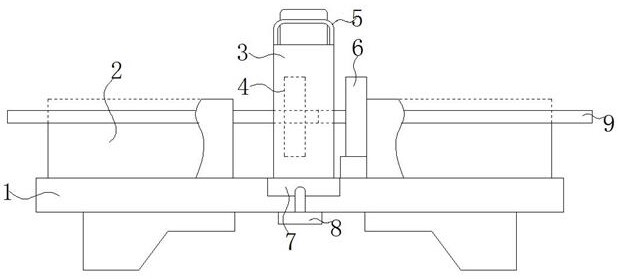
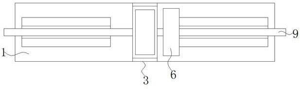
[0041] Specific implementation mode 1: Please refer to Figure 1-12 , the present invention provides a technical solution: an automatic pipe welding machine with a pipe clamping structure, comprising: a machine 1, a welding device 3 and a left clamp 4;

[0042] A support table 2 is installed on both sides of the surface of the machine table 1, and an oval tube 9 is placed on the support table 2. At the same time, a welding device 3 is installed in the middle of the surface of the machine table 1, and a lifting device is installed on both sides of the top of the welding device 3. Hand 5, a left clamp 4 is installed on the left side of the welding device 3, and a right clamp 6 is installed on the right side of the welding device 3, and the right clamp 6 and the left clamp 4 clamp and fix two groups of oval tubes 9 respectively;

[0043] An annular track 32 is installed inside the working frame 31 of the welding device 3, and a welded pipe structure 33 is movably arranged on the ...

specific Embodiment approach 2

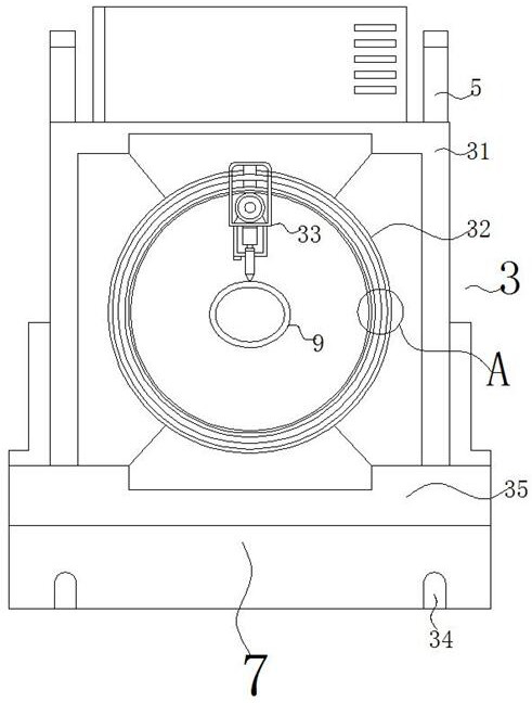
[0046] Embodiment 2: This embodiment is a further limitation of Embodiment 1. The welding device 3, the work frame 31, the annular track 32, the welded pipe structure 33, the screw hole 34, the base 35, the internal rack 36 and the chute 37, and The screw hole 34 is opened on the bottom surface of the mounting seat 7, while the mounting seat 7 is fixedly connected with the base 35, the mounting seat 7 is clamped in the slot opened on the surface of the machine table 1, and the fixing bolt 8 is screwed through the machine table 1. Inside the screw hole 34.

[0047] like Figure 3-4 Shown: the working mode of the welding device 3 is: start the switch of the drive motor 334, so that the output shaft of the drive motor 334 drives the drive gear 339 to rotate, the drive gear 339 meshes with the inner rack 36, and is in the chute 37 and the slider 333 Under the guiding work, the welded pipe structure 33 moves in a left circular motion along the annular track 32, and through the wel...

specific Embodiment approach 3

[0048] Embodiment 3: This embodiment is a further limitation of Embodiment 2. The welded pipe structure 33 includes an installation frame 331 , a limit block 332 , a slider 333 , a drive motor 334 , an installation box 335 , a servo electric cylinder 336 , and a welding head 337 , the distance sensor 338 and the drive gear 339, and the drive gear 339 is adapted to the size of the internal rack 36, and the drive gear 339 is meshed with the internal rack 36. The bottom left side of the installation box 335 is installed with a distance sensor 338. The sensor 338 is electrically connected to the servo electric cylinder 336 through the controller.

[0049] like Figure 3-4 Shown: when the welding head 337 is welding along the outer side wall of the oval tube 9, the cross section of the oval tube 9 is set in an elliptical shape, and when the welding head 337 is moving, the end of the welding head 337 is between the oval tube 9 The distance changes at any time. At this time, the dis...


PUM


Abstract

The automatic pipe welding machine with the pipe clamping structure comprises a machine table, bearing tables are installed on the two sides of the surface of the machine table respectively, oval pipes are placed on the bearing tables, meanwhile, a welding device is installed in the middle of the surface of the machine table, lifting handles are installed on the two sides of the top of the welding device, and a left clamp is installed on the left side in the welding device; and a right clamp is mounted on the right side of the welding device, and the right clamp and the left clamp are used for clamping and fixing the two sets of oval pipes correspondingly. According to the automatic pipe welding machine with the pipe clamping structure, the pipe welding structure annularly moves along the left side of the annular rail, welding work is conducted on the welding positions between two sets of oval pipes through the welding head on the pipe welding structure, the welding mode that the welding head is static and pipelines rotate is replaced, and the situation that when the two sets of pipelines rotate, rotation is not synchronous, and the welding efficiency is improved can be avoided. And dislocation between the two groups of pipelines is avoided.

Description

technical field [0001] The invention relates to the field of pipe welding machines, in particular to an automatic pipe welding machine with a pipe clamping structure. Background technique [0002] The pipe welding machine is mainly a machine for welding steel pipes made by welding steel plates or strip steels after being crimped and formed. It is loved by people because of its high accuracy and high efficiency, and can be seen everywhere in major factories. [0003] When the traditional automatic pipe welding machine is in use, it is impossible to freely adjust the size of the gas fixing structure according to the diameter of different steel pipes, so that some steel pipes cannot be effectively fixed, thus reducing the welding accuracy, and the moving process is also cumbersome. This greatly affects the use of automatic pipe welding machines. [0004] In order to solve the above problems, after searching, the patent with the publication number CN215546385U discloses an adju...

Claims


Application Information

Patent Timeline
IPC IPC(8): B23K31/02B23K37/04
CPCB23K31/027B23K37/0435B23K2101/06Y02P70/10
Inventor 朱伟
Owner 扬州万丰机械制造有限公司
Why Eureka
Try Eureka