Gas taking pipeline structure of GPF differential pressure sensor

A sensor and air intake pipe technology is applied in the field of gas intake pipeline structure of GPF differential pressure sensor to achieve the effect of reducing installation steps, reducing costs and accurate monitoring

Pending Publication Date: 2022-07-05
CHONGQING CHANGAN AUTOMOBILE CO LTD
View PDF5 Cites 0 Cited by
  • Summary
  • Abstract
  • Description
  • Claims
  • Application Information

AI Technical Summary

Problems solved by technology

Undoubtedly, the technical solution disclosed in this patent document is a beneficial attempt in the technical field

Method used


Image

  • Gas taking pipeline structure of GPF differential pressure sensor
  • Gas taking pipeline structure of GPF differential pressure sensor
  • Gas taking pipeline structure of GPF differential pressure sensor

Examples


Embodiment Construction

[0024] The technical solutions of the present invention will be described in detail below with reference to the accompanying drawings.

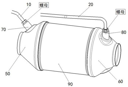
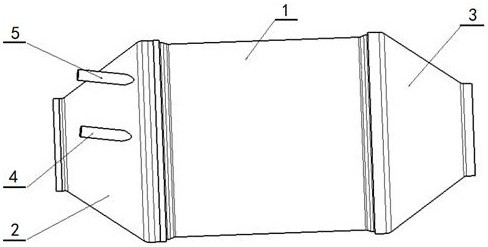
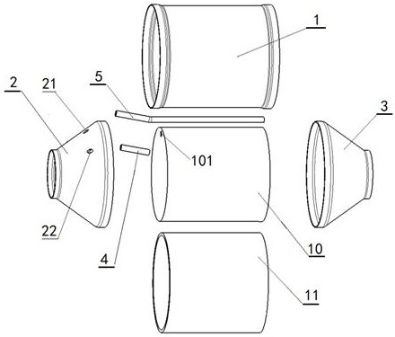
[0025] see Figure 2 to Figure 5 The air intake pipeline structure of a GPF differential pressure sensor shown includes a gasoline engine particle catcher body, a first air intake pipe 4 of a differential pressure sensor and a second air intake pipe 5 of a differential pressure sensor arranged on the gasoline engine particle catcher body, It is characterized in that: the gasoline engine particle catcher body includes a GPF cylinder 1, a ceramic core 10 arranged in the cylinder, a front cone 2 connected to the front end of the cylinder, and a rear cone 3 connected to the rear end of the cylinder; The edge of the core body 10 is provided with a through hole 101 along the axial direction, and a first welding hole 21 and a second welding hole 22 are provided on the conical surface of the front end cone 2; one end of the first air intake pipe 4 of...


PUM


Abstract

The invention relates to a gas taking pipeline structure of a GPF differential pressure sensor. The gas taking pipeline structure comprises a first differential pressure sensor gas taking pipe and a second differential pressure sensor gas taking pipe which are arranged on a gasoline engine particle trap body. The gasoline engine particle trap body comprises a GPF barrel, a ceramic core, a front end cone and a rear end cone. An axial through hole is formed close to the edge of the ceramic core body, and a first welding hole and a second welding hole are formed in the conical surface of the front end cone; one end of a first gas taking pipe of the differential pressure sensor penetrates through a second welding hole of the front-end cone and extends into the GPF barrel, and the other end of the first gas taking pipe is matched and fixed with the second welding hole; one end of a second gas taking pipe of the differential pressure sensor penetrates through the first welding hole of the front end cone, extends into the GPF barrel and penetrates through the through hole in the ceramic core body, and the other end of the second gas taking pipe of the differential pressure sensor is matched and fixed with the first welding hole. The gas taking pipe can be prevented from being exposed in the air, the blockage of an icing assembly in the gas taking pipe is avoided, and the accurate monitoring of the GPF function is ensured.

Description

technical field [0001] The invention relates to an automobile exhaust system, in particular to a gas intake pipeline structure of a GPF differential pressure sensor. Background technique [0002] Gasoline direct injection (GDI) has been widely used in passenger cars due to its advantages of better power and fuel economy. However, because the fuel of the GDI gasoline engine is directly injected into the cylinder, the uneven mixing of oil and gas and the wet wall of the fuel lead to a significant increase in the quality and quantity of particulate matter emissions. More and more stringent regulations require direct injection gasoline engines to maintain stable and low PM emissions in a wider range of operating conditions. The Euro VI emission regulations have stricter restrictions on the quality of particulate matter emissions, and the PM limit has been reduced to 4.5mg / km. The "Light-duty Vehicle Pollutant Emission Limits and Measurement Methods (China Phase VI)" issued on ...

Claims


Application Information

Patent Timeline
Patent Type & Authority Applications(China)
IPC IPC(8): G01L13/00G01L19/06F01N3/021
CPCG01L13/00G01L19/06F01N3/021F01N2900/1406
Inventor 陈龙
Owner CHONGQING CHANGAN AUTOMOBILE CO LTD
Why Eureka
Try Eureka