
Method and device for selecting coding mode

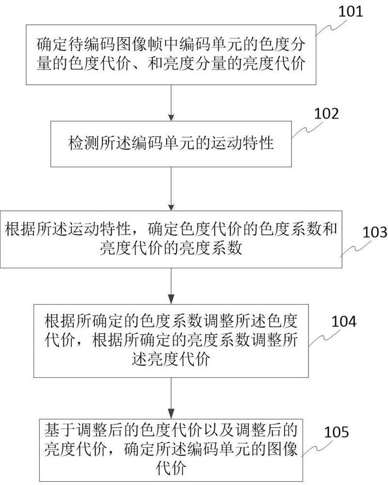
A coding mode and coding unit technology, applied in the field of video coding, can solve the problem of limited influence of image cost, achieve the effect of optimizing the selection of coding parameters, improving the quality of chroma coding, and improving the adaptability

Active Publication Date: 2022-07-05
SHENZHEN MICROBT ELECTRONICS TECH CO LTD
View PDF10 Cites 2 Cited by
  • Summary
  • Abstract
  • Description
  • Claims
  • Application Information

AI Technical Summary

Problems solved by technology

[0007] Although the image cost is the sum of the luma cost and the chroma cost, the chroma cost has limited influence on the image cost

Method used


Image

  • Method and device for selecting coding mode
  • Method and device for selecting coding mode
  • Method and device for selecting coding mode

Examples


Embodiment 1

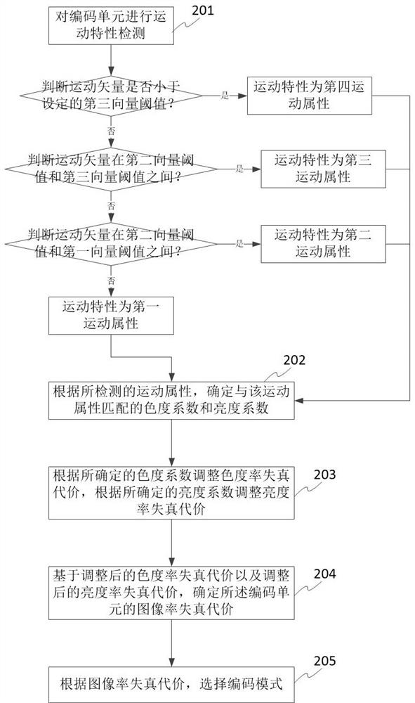
[0101] In image coding, the characteristics of the image sequence have a great influence on the compression performance, the selection of coding modes is also very different in the coding process, and the coding quality of chrominance is also greatly influenced. There are many characteristics of the image sequence, such as motion size, texture, color, shape, etc. In this embodiment, the motion size characteristics of the image sequence are used to adaptively match the chroma coefficients of the chroma rate-distortion cost.

[0102] The following describes the matching of the chroma coefficients of the chroma rate-distortion cost of one coding unit by the motion characteristics as an example.

[0103] see figure 2 shown, figure 2 This is a schematic flowchart of a method for selecting an image rate distortion cost according to an embodiment of the present application. For any coding unit in the image frame to be coded, perform the following steps:

[0104] Step 201, perfor...

Embodiment 2

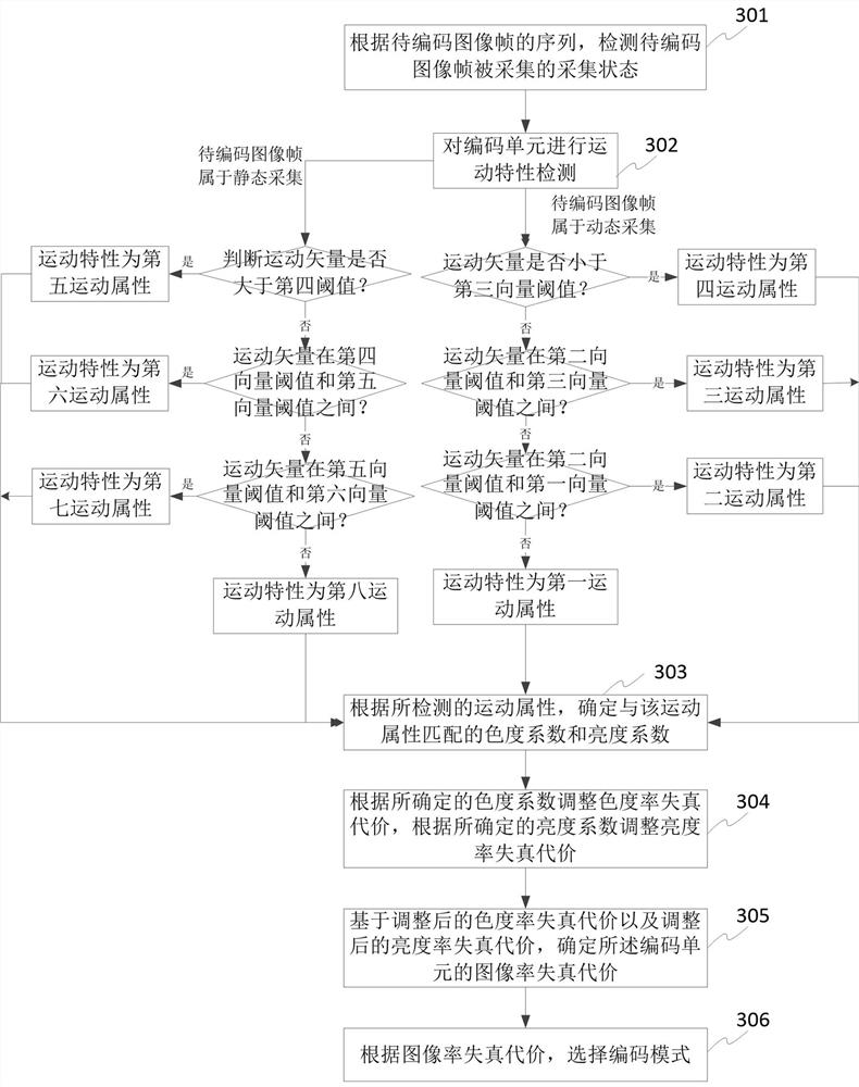
[0158] see image 3 shown, image 3 This is a schematic flowchart of a method for selecting an image rate-distortion cost in Embodiment 2 of the present application. For any coding unit in the image frame to be coded, perform the following steps:

[0159] Step 301: Determine the acquisition state in which the image frame to be encoded is acquired, wherein the acquisition state includes a static acquisition state and a dynamic acquisition state,

[0160] As an example, according to the sequence of image frames to be encoded, the acquisition state of the image frames to be encoded is detected, for example,

[0161] According to the sequence of image frames to be encoded, determine whether the image frame to be encoded has global motion, if not, it means that the image capture device used to capture the image frame is fixed, that is, the current image frame belongs to the static capture state, otherwise, then It means that the image acquisition device is not fixed, that is, th...


PUM


Abstract

The invention discloses a coding mode selection method, which comprises the steps of determining the chroma cost of a chroma component and the brightness cost of a brightness component of a coding unit in a to-be-coded image frame, detecting the motion characteristic of the coding unit, determining the chroma coefficient of the chroma cost and the brightness coefficient of the brightness cost according to the motion characteristic, and selecting a coding mode according to the chroma coefficient and the brightness coefficient. Adjusting the chromaticity cost according to the determined chromaticity coefficient, and adjusting the brightness cost according to the determined brightness coefficient; determining the image cost of the coding unit based on the adjusted chromaticity cost and the adjusted brightness cost; wherein the chromaticity coefficient and the brightness coefficient are used for enabling the first cost contribution of the adjusted chromaticity cost in the image cost to be increased; and selecting a coding mode according to the image cost. According to the invention, the chromaticity cost in the image cost is increased, so that the chromaticity is maximized with smaller brightness loss.

Description

technical field [0001] The present invention relates to the field of video encoding, and in particular, to a method for selecting an encoding mode. Background technique [0002] In image / video encoding techniques, the encoding mode selection of each coding unit in an image frame to be encoded is usually matched based on image cost. [0003] Take video encoding as an example. In current video coding standards, frameworks such as H.264 / H265 / H.266 include luma coding and chroma coding. In current practice, on the one hand, the chrominance coding in the standard is directly affected by the luminance coding. For example, the motion vector (mv, motion vector) used in the inter-frame prediction is directly derived from the motion vector of the luminance. On the other hand, the picture cost RDOcost for coding mode selection for each coding unit (prediction unit) is calculated as: [0004] RDOcost=RDOLumaCost+RDOChromaUCost+RDOChromaVCost [0005] in, [0006] RDOLumaCost is the...

Claims


Application Information

Patent Timeline
Patent Type & Authority Applications(China)
IPC IPC(8): H04N19/103H04N19/147H04N19/186
CPCH04N19/103H04N19/147H04N19/186
Inventor 胡祥斌翟云杨作兴宋剑军刘红
Owner SHENZHEN MICROBT ELECTRONICS TECH CO LTD
Learn More