Head cooling device for emergency nursing
A cooling device and head technology, applied in physical therapy, heating appliances for therapeutic treatment, cooling appliances for therapeutic treatment, etc., can solve problems such as unfavorable recovery, excessive loss of skin surface water, and unfavorable recovery of patients
- Summary
- Abstract
- Description
- Claims
- Application Information
AI Technical Summary
Problems solved by technology
Method used
Image

Examples
Embodiment 1
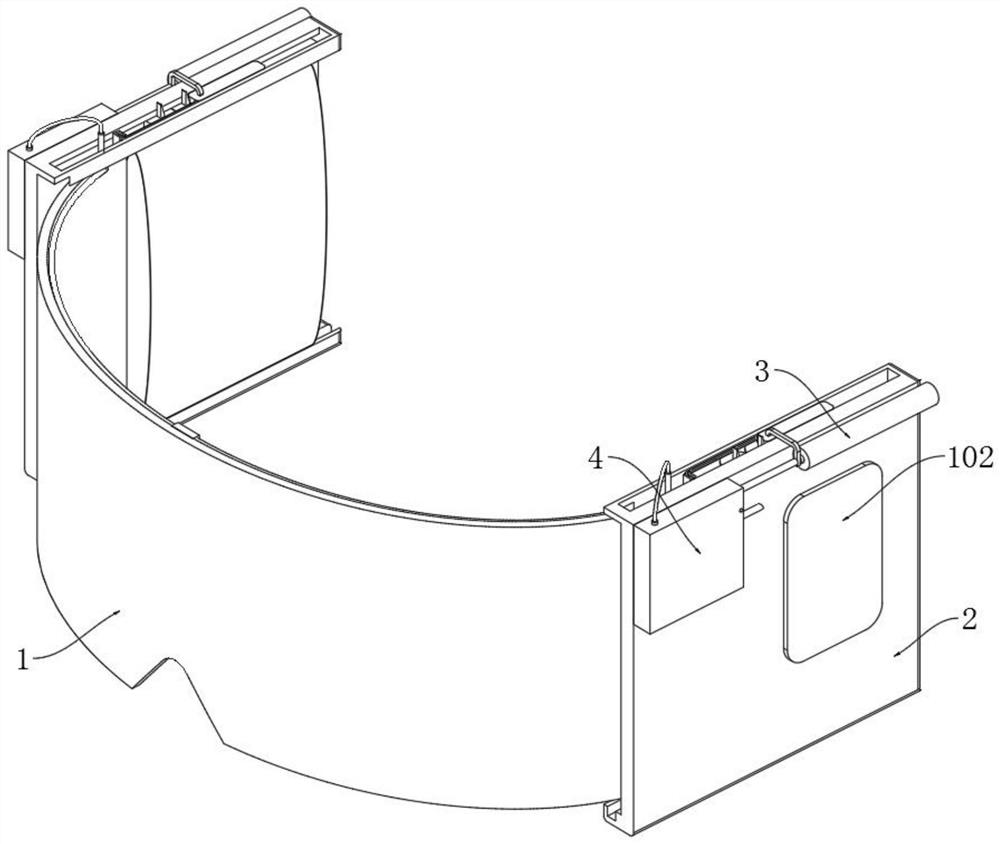
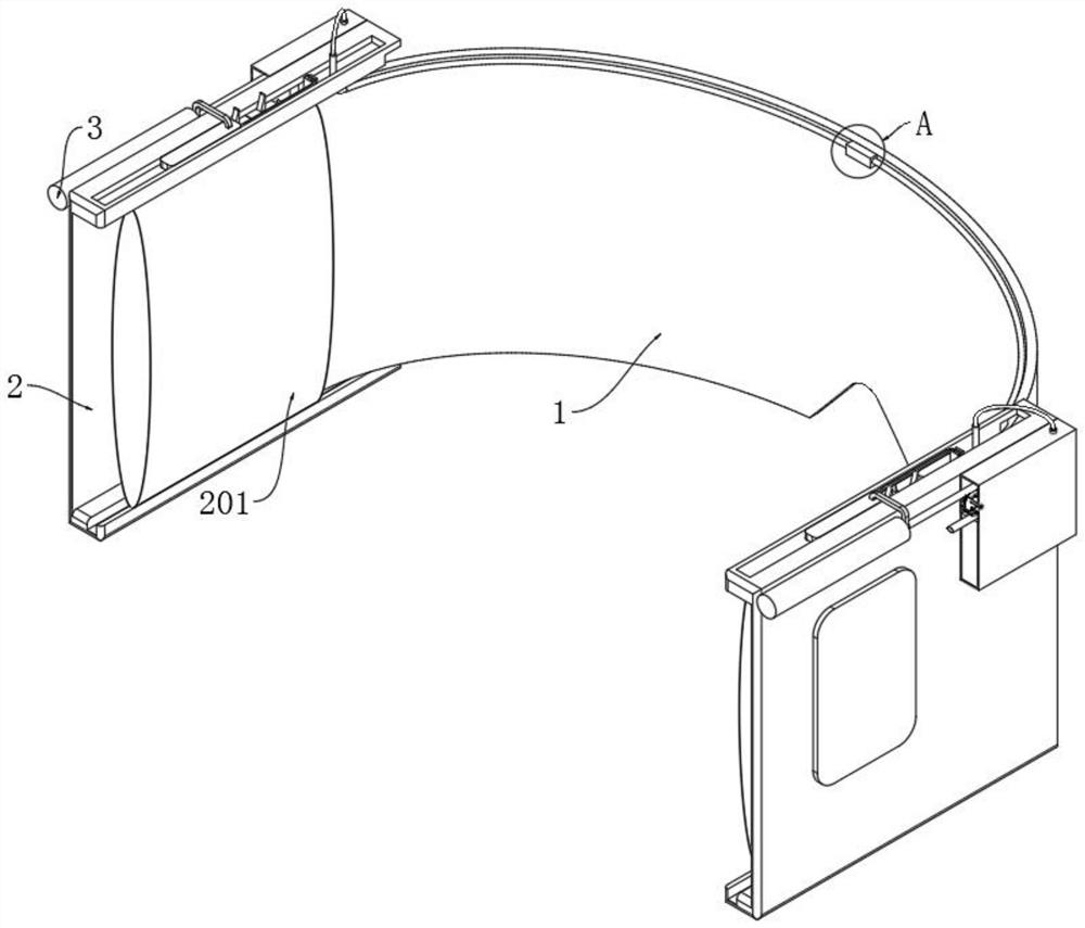
[0039] like Figure 1 to Figure 3As shown, the emergency nursing head cooling device in this embodiment includes a cooling plate 1, a temperature and humidity detector 101 on the surface of the cooling plate 1, a side chute plate 2 installed on both sides of the cooling plate 1, and a side chute plate 2 on the surface. Display screen 102; the inside of the side chute plate 2 is fixedly installed with a liquid bladder 201, the outer surface of the side chute plate 2 is installed with a micro pole 3, and the output shaft of the micro pole 3 is installed with a connection Plate 301, a sliding plate 302 is installed at the end of the connecting plate 301, and the sliding plate 302 is located in the groove on the surface of the side chute plate 2, a separation mechanism is installed on the surface of the sliding plate 302, and a driving supply is installed on the connecting plate 301 A cooling mechanism is installed at the edge of the surface of the cooling plate 1 .
[0040] At w...
Embodiment 2
[0042] On the basis of Example 1:
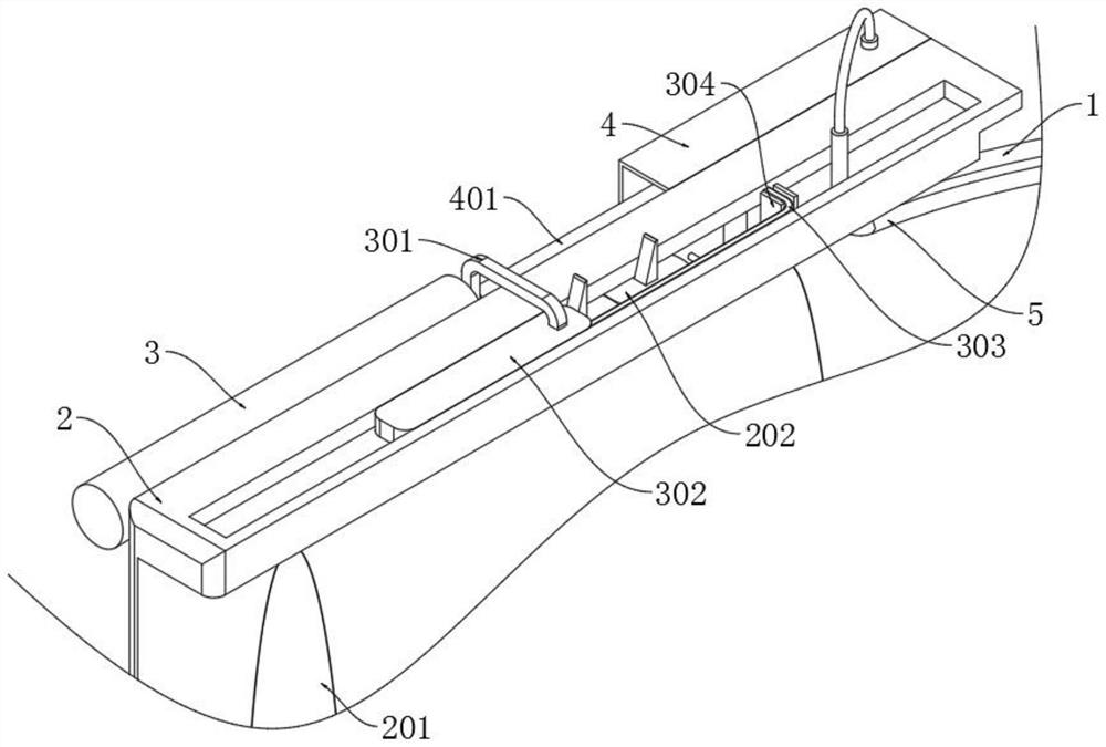
[0043] like image 3 As shown, the emergency nursing head cooling device in this embodiment, specifically, the separation mechanism includes a connecting rod 303 and a concave block 304, the connecting rod 303 is installed on the surface of the slide plate 302, the concave block 304 is installed on the top of the cooling plate 1, and the concave block 304 is installed on the top of the cooling plate 1. Block 304 is used in conjunction with link 303 .
[0044] At work: as image 3 As shown, when the user wears the whole device, when the temperature and humidity detector 101 detects that the user's head is too humid, the micro pole 3 works and drives the connecting plate 301 to move out, and the connecting plate 301 drives the fixedly connected When the sliding plate 302 moves, the movement of the sliding plate 302 will drive the connecting rod 303 to move. Because the concave block 304 is fixedly connected with the cooling plate 1, the conn...
Embodiment 3
[0046] On the basis of Examples 1 and 2:
[0047] like image 3 As shown, the present embodiment of the emergency nursing head cooling device, further, a piston tube 202 is also installed in the groove of the side chute plate 2, and the output part of the piston tube 202 is located on the moving path of the sliding plate 302, and The bottom of the piston tube 202 is connected to the liquid bladder 201 through a hose.
[0048] At work: as image 3 As shown, on the basis of the movement of the sliding plate 302, since the output part of the piston tube 202 is located on the moving path of the sliding plate 302, the movement of the sliding plate 302 will squeeze the movable part of the piston tube 202, and the movable part of the piston tube 202 will squeeze It will push the internal piston movement, the piston movement will generate gas, and the gas will be transported to the inside of the liquid bladder 201 through the hose, which will cause the liquid bladder 201 to expand s...
PUM
 Abstract
Description
Claims
Application Information
 - R&D
- Intellectual Property
- Life Sciences
- Materials
- Tech Scout
- Unparalleled Data Quality
- Higher Quality Content
- 60% Fewer Hallucinations
Browse by: Latest US Patents, China's latest patents, Technical Efficacy Thesaurus, Application Domain, Technology Topic, Popular Technical Reports.
© 2025 PatSnap. All rights reserved.Legal|Privacy policy|Modern Slavery Act Transparency Statement|Sitemap|About US| Contact US: help@patsnap.com