Automatic valve assembling equipment

An assembly equipment and automation technology, applied in the direction of assembly machines, metal processing equipment, climate sustainability, etc., can solve problems such as low production efficiency and low degree of automation, and achieve the effects of improving efficiency, improving accuracy, and ingenious design

Active Publication Date: 2022-07-08
LIANKE VALVE CO LTD
View PDF5 Cites 0 Cited by
  • Summary
  • Abstract
  • Description
  • Claims
  • Application Information

AI Technical Summary

Problems solved by technology

[0004] However, there are following problems in this technical solution: in the process of assembly, the knob, valve core and valve cover need to be put into the valve body in turn and assembled with the valve body. However, in this technical solution, the knob, valve core and valve cover need to be assembled manually. Manually put in, resulting in a low degree of automation and low production efficiency

Method used


Image

  • Automatic valve assembling equipment
  • Automatic valve assembling equipment
  • Automatic valve assembling equipment

Examples


Embodiment 1

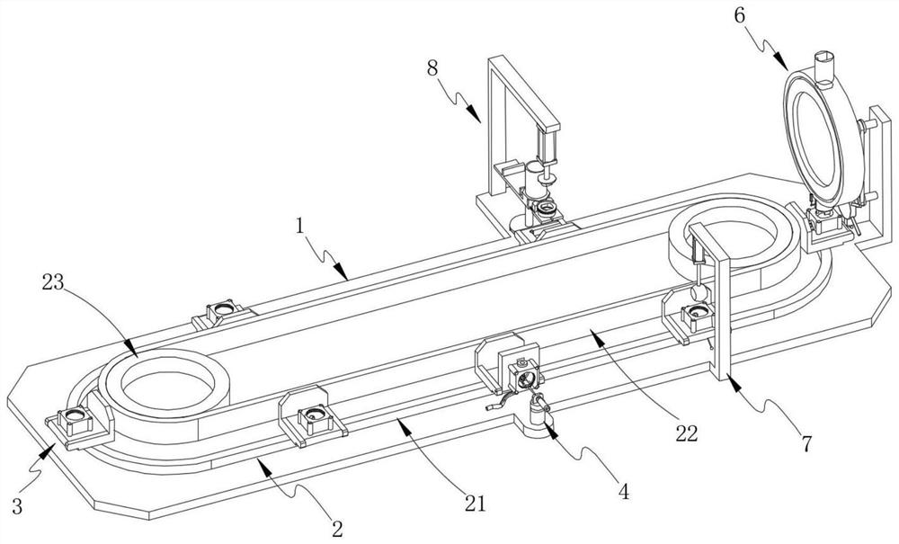
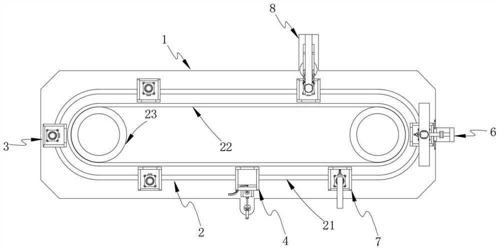
[0054] like figure 1 and image 3 As shown, the present invention provides an automatic valve assembly equipment, comprising: a workbench 1; an annular drive part 2, which is installed on the workbench 1; a material placement plate 3, which is arranged on the annular drive part 2 on the transfer valve body; also includes:

[0055] The first assembly part 4, the first assembly part 4 is set on the workbench 1 for installing the knob in the valve body; the transmission part 5, the transmission part 5 is set on one side of the workbench 1 for transmitting the knob; the second assembly part 6 , the second assembly part 6 is arranged on the workbench 1 for installing the valve core in the valve body;

[0056] The third assembly part 8 is provided on the workbench 1 for installing the valve cover in the valve body.

[0057] In the present invention, the valve body is transmitted through the material placing plate 3; the first assembly part 4 is used to install the knob in the va...

Embodiment 2

[0083] like Figure 18 As shown, the same or corresponding components as those in the first embodiment are given the corresponding reference numerals as in the first embodiment. For the sake of brevity, only the points of difference from the first embodiment are described below. The difference between the second embodiment and the first embodiment is:

[0084] This embodiment also includes a positioning adjustment part 7, which is arranged on one side of the worktable 1 to adjust the knob and the valve core for precise assembly;

[0085] preferably, as Figure 18 and Figure 19 As shown, the positioning adjustment component 7 includes: an adjustment component 71, which is arranged on the material placing plate 3 for adjusting the angle of the knob; a guide component 72, which is arranged in the discharge pipe 634 to discharge the valve core Provide guidance.

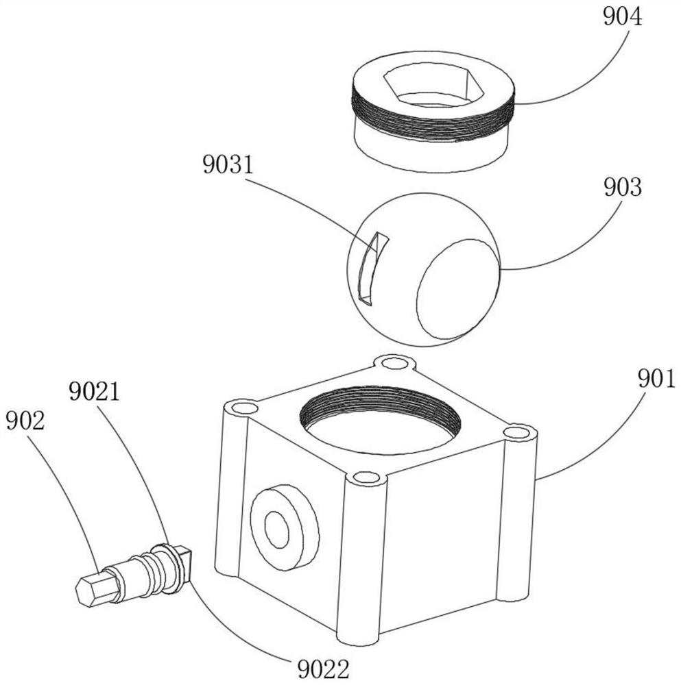
[0086] like figure 2 As shown, the end of the knob is provided with a word block 9022, which is used to match the...


PUM


Abstract

The invention provides automatic valve assembling equipment. The automatic valve assembling equipment comprises a workbench; the annular driving part is mounted on the working table; the material placing plate is arranged on the annular driving part and is used for conveying the valve body; the first assembling part is arranged on the workbench and used for installing a knob in the valve body; the conveying part is arranged on one side of the workbench and used for conveying knobs; the second assembling part is arranged on the workbench and used for installing a valve element in the valve body. The valve body is conveyed through the material placing plate, the first assembling part is used for installing a rotary knob in the valve body, the conveying part is used for conveying the rotary knob, the second assembling part is used for installing a valve element in the valve body, the third assembling part is used for installing a valve deck in the valve body, high-automation production of the valve is achieved, and the production efficiency is greatly improved.

Description

technical field [0001] The invention relates to the technical field of valve production, in particular to an automatic valve assembly equipment. Background technique [0002] The valve is a control component in the fluid conveying system, with functions such as cut-off, regulation, diversion, prevention of backflow, stabilization, diversion or overflow and pressure relief, such as figure 2 Shown is a valve in the prior art, including a valve body 901 , a knob 902 , a valve core 903 and a valve cover 904 . [0003] Chinese Patent Application No. 201510824045.5 discloses a mechanical device and an assembling method of an automatic assembly system for a square ball valve, which realizes the integration of the square valve assembly and the inflation process, simplifies the process flow of the square valve assembly and detection, and the system can realize the Automatic assembly improves the assembly efficiency of the square valve; compared with the impact of worker skills and e...

Claims


Application Information

Patent Timeline
Patent Type & Authority Applications(China)
IPC IPC(8): B23P21/00
CPCB23P21/004Y02P70/50
Inventor 陈光辉陈光文张银弟姜小珍陈龙向涛
Owner LIANKE VALVE CO LTD
Why Eureka
Try Eureka