
Polishing machine for hardware machining and clamping mechanism of polishing machine

A polishing machine and hardware technology, which is applied in the field of hardware processing, can solve the problems of large manpower input, difficulty in collecting debris, unfavorable efficiency of elbow polishing, etc., and achieve the effect of improving efficiency and polishing effect

Inactive Publication Date: 2022-07-08
宋荣辉
View PDF0 Cites 0 Cited by
  • Summary
  • Abstract
  • Description
  • Claims
  • Application Information

AI Technical Summary

Problems solved by technology

[0002] Hardware refers to the tools obtained by processing and casting gold, silver, copper, iron, tin and other metals, which are used to fix things, process things, decorate, etc. Common hardware has 90-degree angle bends. When the inside of the pipe is polished, the common practice is that the operator puts the elbow on the polishing roller, and supports the elbow to polish the inside of the elbow, or uses a disintegration clamp to clamp and fix the elbow, and then puts the polishing roller Extending into the elbow for polishing, the entire polishing process requires a lot of manpower, and the position of the elbow needs to be frequently moved to polish the inside of the two pipe ends during polishing, which is not conducive to improving the efficiency of elbow polishing. In addition, in the process of elbow polishing Debris will be generated, and traditional polishing machines are not easy to collect debris, which will affect the cleanliness and tidiness of the working environment

Method used


Image

  • Polishing machine for hardware machining and clamping mechanism of polishing machine
  • Polishing machine for hardware machining and clamping mechanism of polishing machine
  • Polishing machine for hardware machining and clamping mechanism of polishing machine

Examples


Embodiment Construction

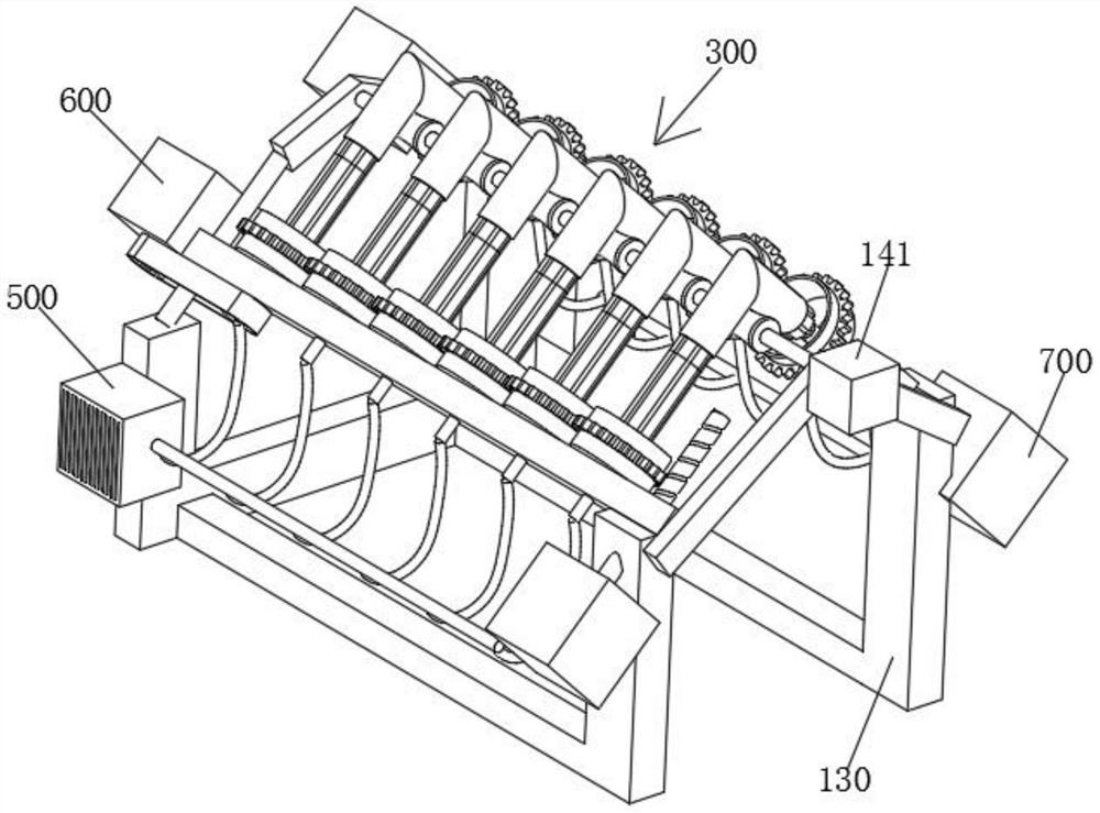
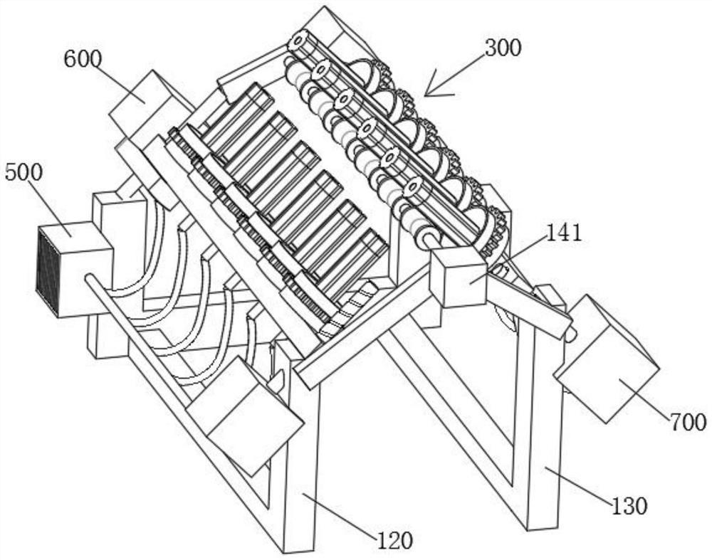
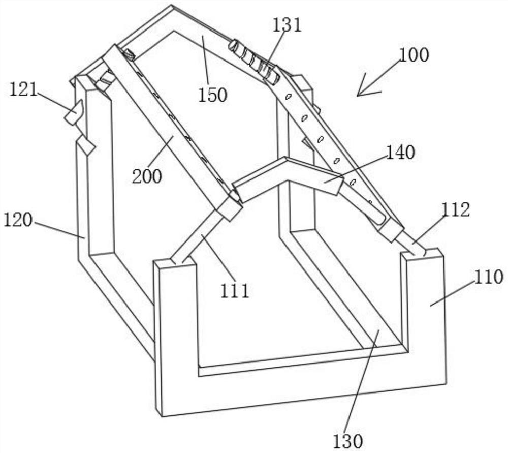
[0028]The technical solutions in the embodiments of the present invention will be clearly and completely described below with reference to the embodiments of the present invention. Obviously, the described embodiments are only a part of the embodiments of the present invention, rather than all the embodiments. Based on the embodiments of the present invention, all other embodiments obtained by those of ordinary skill in the art without creative efforts shall fall within the protection scope of the present invention.

[0029] see Figure 1-9 As shown, a polishing machine for hardware processing and its clamping mechanism includes a frame 100, the frame 100 includes a grooved plate 110, and one side of the grooved plate 110 is fixed with an L-shaped column 1 120 and an L-shaped column 2 130, the two ends of the top surface of the grooved plate 110 are respectively fixed with a guide shaft one 111 and a guide shaft two 112, a connecting block one 140 is fixed between the guide sh...


PUM


Abstract

The invention relates to the technical field of hardware machining, in particular to a polishing machine for hardware machining and a clamping mechanism thereof.The polishing machine for hardware machining comprises a rack, the rack comprises a C-shaped plate, a first L-shaped column and a second L-shaped column are fixed to one side of the C-shaped plate, and the top end of the first L-shaped column and the top end of the second L-shaped column are rotationally connected with a first screw and a second screw correspondingly; a cross beam is arranged between the first screw and the first guide shaft, a cross beam is arranged between the second screw and the second guide shaft, and a plurality of polishing mechanisms are arranged on one side of each cross beam at equal intervals. According to the elbow pipe polishing and clamping device, the two adjacent polishing rollers which are arranged at the 90-degree angle are matched to clamp an elbow pipe and polish the interior of the elbow pipe at the same time, and the two adjacent polishing rollers can be driven by the first screw and the second screw to exchange positions at the inner corner of the elbow pipe for polishing, so that the elbow pipe polishing and clamping efficiency can be improved; and the end opening of the bent pipe is arranged downwards to be combined with the storage cover, so that chippings generated during polishing are conveniently collected, and the cleanliness and tidiness of the working environment are guaranteed.

Description

technical field [0001] The invention relates to the technical field of hardware processing, in particular to a polishing machine for processing hardware and a clamping mechanism thereof. Background technique [0002] Hardware refers to tools obtained by processing and casting with metals such as gold, silver, copper, iron, tin, etc., which are used to fix things, process things, decorate, etc. When polishing the inside of the tube, it is common practice for the operator to sleeve the elbow on the polishing roller, and support the elbow to polish the interior of the elbow, or use a disintegration jig to clamp and fix the elbow, and then place the polishing roller. Extending into the elbow for polishing, the entire polishing process requires a lot of manpower, and the position of the elbow needs to be moved frequently to polish the inside of the two pipe ends, which is not conducive to improving the efficiency of elbow polishing. In addition, during the elbow polishing process...

Claims


Application Information

Patent Timeline
Patent Type & Authority Applications(China)
IPC IPC(8): B24B29/08B24B27/00B24B27/06B24B41/02B24B41/06B24B41/00B24B55/06
CPCB24B29/08B24B27/0076B24B27/06B24B41/02B24B41/06B24B41/005B24B55/06Y02P70/10
Inventor 宋荣辉周军
Owner 宋荣辉
Learn More