Relay plastic shell injection molding production device and method capable of automatically taking parts

A technology of plastic casing and automatic pickup, applied in the field of relay casing production, can solve the problems of slow labor efficiency, inability to take away, and the relay casing falling on the ground, etc., so as to improve production efficiency and automation level, and reduce labor intensity. Effect

Pending Publication Date: 2022-07-08
嘉兴市群峰电器股份有限公司
View PDF6 Cites 0 Cited by
  • Summary
  • Abstract
  • Description
  • Claims
  • Application Information

AI Technical Summary

Problems solved by technology

[0003] After the injection molding of the relay casing is completed, the relay casing is usually ejected from the mold base directly through the thimble, so that the relay casing falls directly from the mold base to the ground; or manually ejected to the inside of the mold base. Manual r

Method used


Image

  • Relay plastic shell injection molding production device and method capable of automatically taking parts
  • Relay plastic shell injection molding production device and method capable of automatically taking parts
  • Relay plastic shell injection molding production device and method capable of automatically taking parts

Examples


Example Embodiment

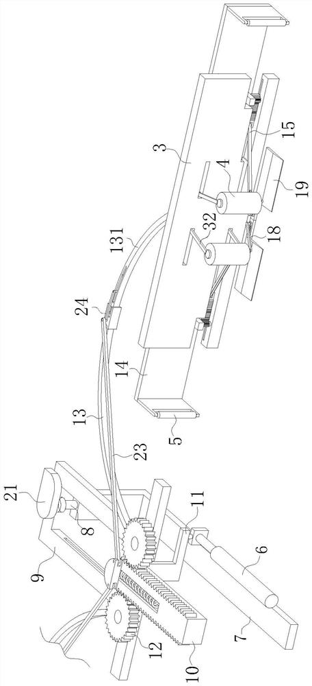
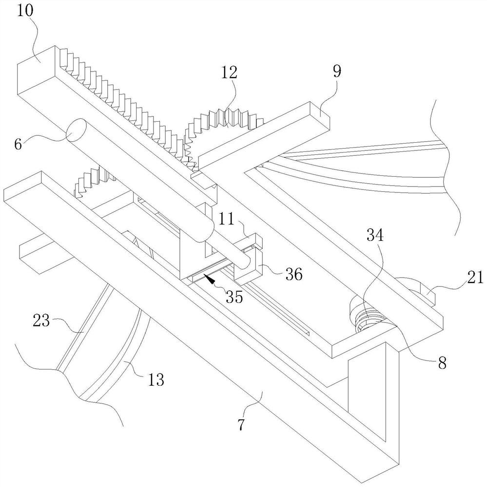
[0044] Embodiment 1: The connecting group includes two first connecting pieces 15; the two first connecting pieces 15 are respectively rotatably connected with the two supporting pieces 32, and both sets of the first connecting pieces 15 are rotatably connected with a second connecting piece 15. Two racks 16, the second racks 16 are slidingly connected with the clamping plate 3, and the two second racks 16 are meshed with the two second gears 17 respectively; during operation, when the first support roller 4 rotates When the supporting member 32 is driven to expand, the supporting member 32 will push the first connecting member 15, and when the first connecting member 15 is pushed, the first connecting member 15 will push the second rack 16 when the first connecting member 15 is pushed. When the rack 16 is pushed, it will mesh with the second gear 17 when the clamping plate 3 slides, and then drive the L-shaped plate 14 to rotate, so that the two second support rollers 5 enter ...

Example Embodiment

[0045] Embodiment 2: the connection group includes two third electric telescopic rods 31; the fixed ends of the two third electric telescopic rods 31 are both fixedly connected to the clamping plate 3, and the third electric telescopic rods 31 are The telescopic ends are fixedly connected with a third rack 29, and the third racks 29 are respectively meshed with the two second gears 17; during operation, when the clamping plate 3 drives the first support roller 4 to contact the relay housing, The third electric telescopic rod 31 is activated and then pushes the third rack 29 to mesh with the second gear 17, so that the second gear 17 drives the L-shaped plate 14 to rotate, so that the second support roller 5 enters the groove of the relay housing; Compared with Embodiment 1, the connection group in this embodiment only needs to drive the third rack 29 through the expansion and contraction of the third electric telescopic rod 31 to rotate the second gear 17, so that the L-shaped ...


PUM


Abstract

The invention belongs to the technical field of relay shell production, and discloses a relay plastic shell injection molding production device capable of automatically taking parts, which comprises a bottom plate and a lower die holder, the bottom plate is positioned below the lower die holder, and a jacking group for jacking out a relay shell is arranged between the bottom plate and the lower die holder; the relay shell is clamped and supported through the first supporting roller and the second supporting roller, it is ensured that the relay shell cannot fall off when the driving assembly drives the clamping plate to move, and it is ensured that the relay shell cannot be broken or cannot cause surface scratches to affect the product quality; and manual participation is not needed, and when a clamping plate moves to a designated position, a driving assembly enables a first supporting roller and a second supporting roller to make contact to clamp the relay shell, so that the relay shell can automatically fall off.

Description

technical field [0001] The invention relates to the technical field of relay casing production, in particular to an injection molding production device and method for a relay plastic casing that can automatically pick up parts. Background technique [0002] Injection molding is a method of producing shapes for industrial products. Products usually use rubber injection molding and plastic injection molding. Injection molding can also be divided into injection molding and die casting. Injection molding machine (referred to as injection machine or injection molding machine) is the main molding equipment for making thermoplastics or thermosetting plastics into various shapes of plastic products using plastic molding molds. Injection molding is achieved by injection molding machines and molds. [0003] When the relay shell is injection molded, the relay shell is generally pushed out from the mold base directly through the ejector pin, so that the relay shell directly falls from...

Claims


Application Information

Patent Timeline
IPC IPC(8): B29C39/02B29C39/36B29C39/22
CPCB29C39/02B29C39/36B29C39/22
Inventor 毛怡
Owner 嘉兴市群峰电器股份有限公司
Why Eureka
Try Eureka